Clamping device

Inactive Publication Date: 2011-11-10
HIESTAND KARL
View PDF0 Cites 11 Cited by
  • Summary
  • Abstract
  • Description
  • Claims
  • Application Information

AI Technical Summary

Benefits of technology

[0006]The object of the present invention is, therefore, to provide a clamping device of the aforementioned type wherein the servomotor only has to be taken into operation in order to clamp and to unclamp a workpiece, and is therefore only in a driving connection with the clamping device in these operating conditions. Above all, however, during machining of a workpiece, all the components of the clamping device involved in the force transmission are in a firm driving connection with the machine spindle, with the effect that return movements of the power-operated chuck are excluded. In addition, the power-operated chuck makes it possible to achieve a defined re-clamping. Accordingly, a reliable operating method of the clamping device is guaranteed at all times.
[0019]Furthermore, it is appropriate for the drive motor of the machine tool to be electrically connected to the servomotor by means of a control unit. This makes it possible to control the servomotor of the clamping device, depending on the rotation speed of the drive motor of the machine tool, in such a way that the rotation speed of the servomotor for increasing or reducing the clamping force of the power-operated chuck during the machining process can be adjusted by means of the control unit so that the servomotor rotates synchronously with the rotation speed of the drive motor for coupling the drive gear with the sliding sleeve, and the servomotor can be driven with increased or reduced speed in relation to the synchronous speed in order to increase or reduce the clamping force.
[0020]If a clamping device is configured in accordance with the present invention, it precludes any uncontrolled change in the clamping force of the power-operated chuck during a working procedure, and precludes the power-operated chuck from coming open spontaneously. Due to the fact that the servomotor is only in a driving connection with the components involved in power transmission for clamping and releasing a workpiece, the components can only trigger adjusting movements under these operating conditions. During a working procedure, however, the components involved in power transmissions are connected to the machine spindle via the sliding sleeve, and are therefore blocked. A change in position of the draw rod, and therefore unclamping in the power-operated chuck, is therefore impossible.
[0022]As a result, and with a low design complexity, a clamping device is provided which not only has a relatively straightforward design structure, thereby allowing it to be manufactured economically, but also, and above all, guarantees reliable operation at all times with a low energy consumption, because the servomotor can be taken out of operation during machining, and has a wide range of uses.

Problems solved by technology

Although the complexity of the design is therefore considerable, the power-operated chuck is not secured during a machining process.
The clamping device of prior art can therefore not be used in practice.

Method used


Image

  • Clamping device
  • Clamping device
  • Clamping device

Examples


Embodiment Construction

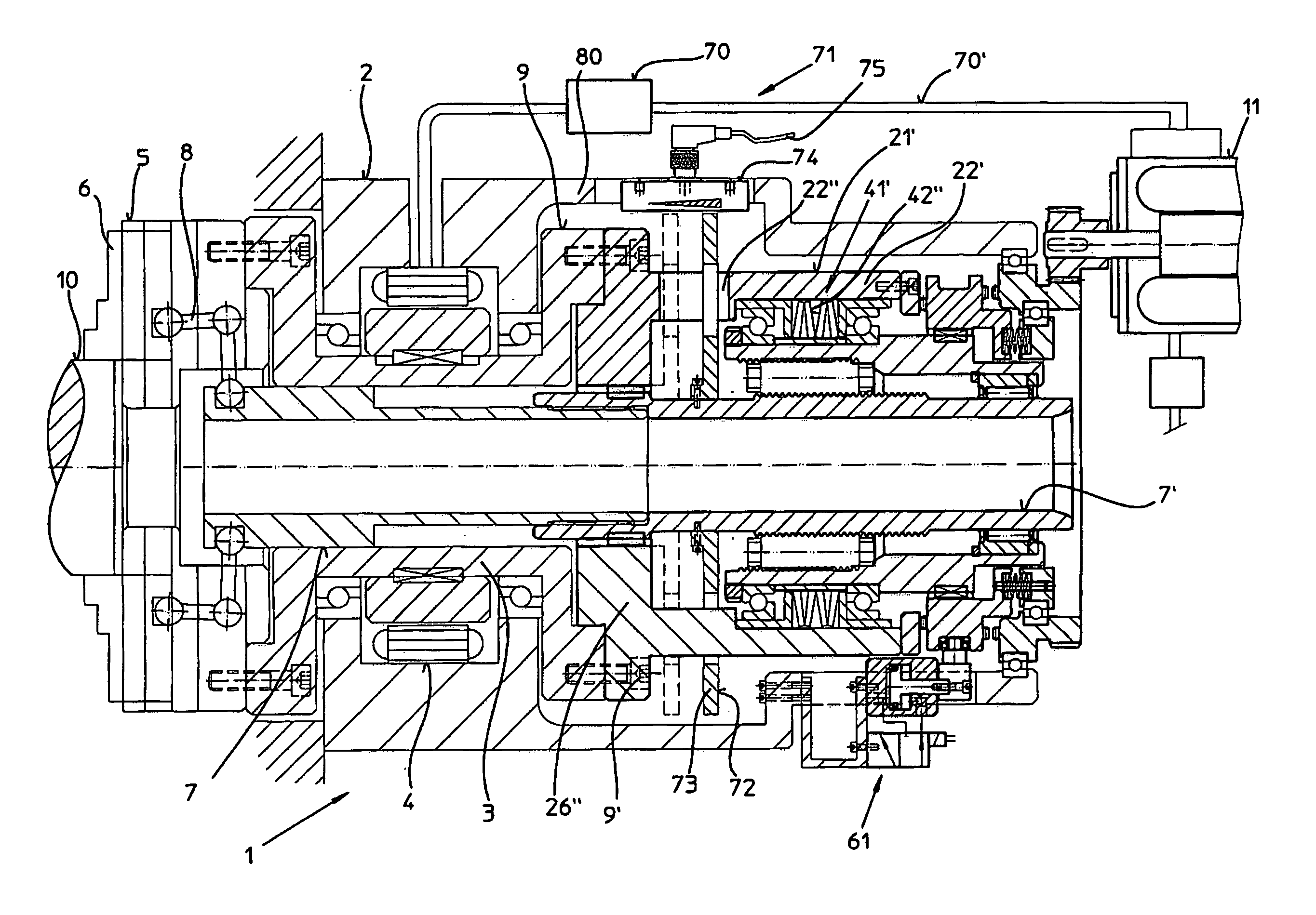
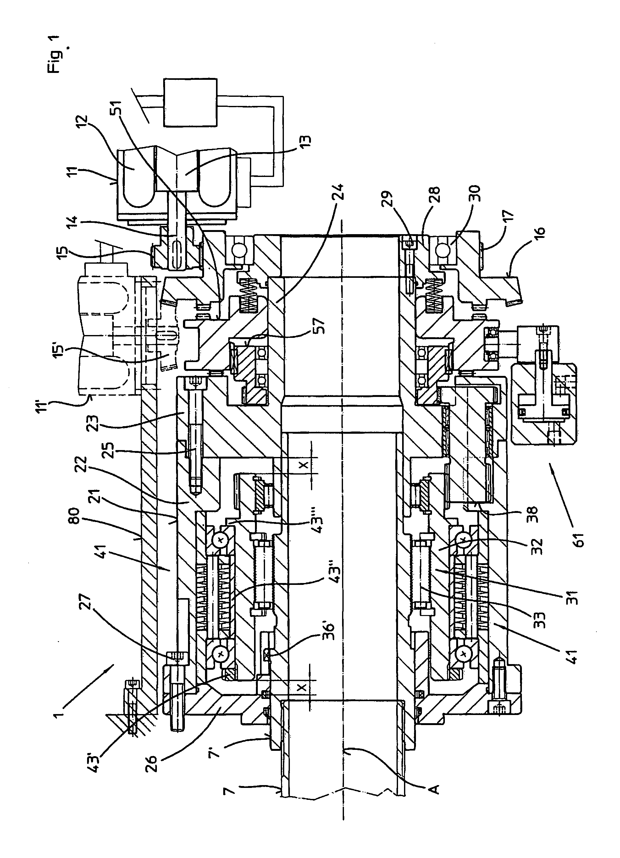
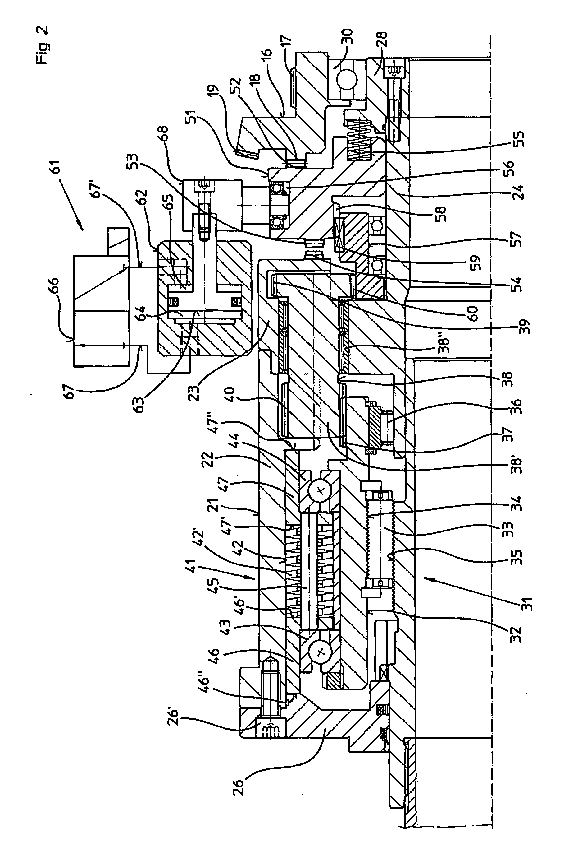
[0029]The clamping device illustrated in FIGS. 1 and 5 and identified by 1, is used for actuating a power-operated chuck 5 (FIG. 5) arranged on a machine tool 2, by means of radially adjustable clamping jaws 6 by which a workpiece 10 to be machined can be clamped in the chuck 5. The clamping jaws of the power-operated chuck 5 in this case can be actuated via relay levers 8 by an axially adjustable, two-piece draw rod 7, 7′ that is in driving connection with an electric servomotor 11 that has a changeover function by means of a movement converter 31 or 31′. The movement converter 31 or 31′ converts rotational movements of the servomotor 11 into axial feed movements of the draw rod 7, 7′.

[0030]The servomotor 11 consists of a stator 12 in a fixed location located with its axis in parallel to the lengthways axis A of the clamping device 1, and of a rotor 13 with a pinion 15 connected in a rotationally fixed arrangement with a rotor shaft 14 of the rotor 13, which engages in gearing 17 a...


PUM


Abstract

A clamping device for machine tools is provided with a chuck, the clamping jaws of which are actuated by a draw rod, the clamping device having of a servomotor, a movement converter and a force accumulator, the servomotor is connectable to the movement converter for triggering clamping movements. The movement converter and the force accumulator are disposed in a housing connectable to the machine spindle, and in clamping position of the clamping device, the sliding sleeve can be decoupled from the servomotor, and the housing can be connected to the movement converter by means of the sliding sleeve.The servomotor is operated only to clamp and unclamp a workpiece, and is in a driving connection with the clamping device in operating conditions. All components of the clamping device involved in power transmission are in driving connection with the machine spindle during the machining of the workpiece.

Description

BACKGROUND OF THE INVENTION[0001]1. Field of the Invention[0002]The present invention relates to a clamping device for machine tools, and that provided with a power-operated chuck for holding a workpiece, for example, and clamping jaws which can be actuated using the clamping device by means of an axially moveable draw rod, in which the clamping device includes an electric servomotor with a changeover function for triggering clamping movements, a movement converter for converting the adjustment movements of the rotor shaft of the servomotor into axial movements of the draw rod required for actuating the clamping jaws, and a force accumulator for maintaining the clamping force, as well as a process for controlling the servomotor according to the rotation speed of the drive motor of the machine tool.[0003]2. Description of the Prior Art[0004]A clamping device of this kind is disclosed in EP 0 228 007 A2. In this embodiment, as soon as electrical energy is applied to the servomotor, th...

Claims


Application Information

Patent Timeline
IPC IPC(8): B23B31/26B23Q17/00B23B31/36
CPCB23B31/28Y10T279/27Y10T279/21
Inventor HIESTAND, KARL
Owner HIESTAND KARL
Why Eureka
Try Eureka