Charged particle beam applied apparatus
a technology of charged particles and applied apparatuses, which is applied in the direction of material analysis using wave/particle radiation, instruments, nuclear engineering, etc., can solve the problems of long time, improvement of specimen processing speed, and difficulty in shortening the distance between the positions illuminated by the electron source, so as to achieve the effect of convenient implementation
- Summary
- Abstract
- Description
- Claims
- Application Information
AI Technical Summary
Benefits of technology
Problems solved by technology
Method used
Image
Examples
embodiment 1
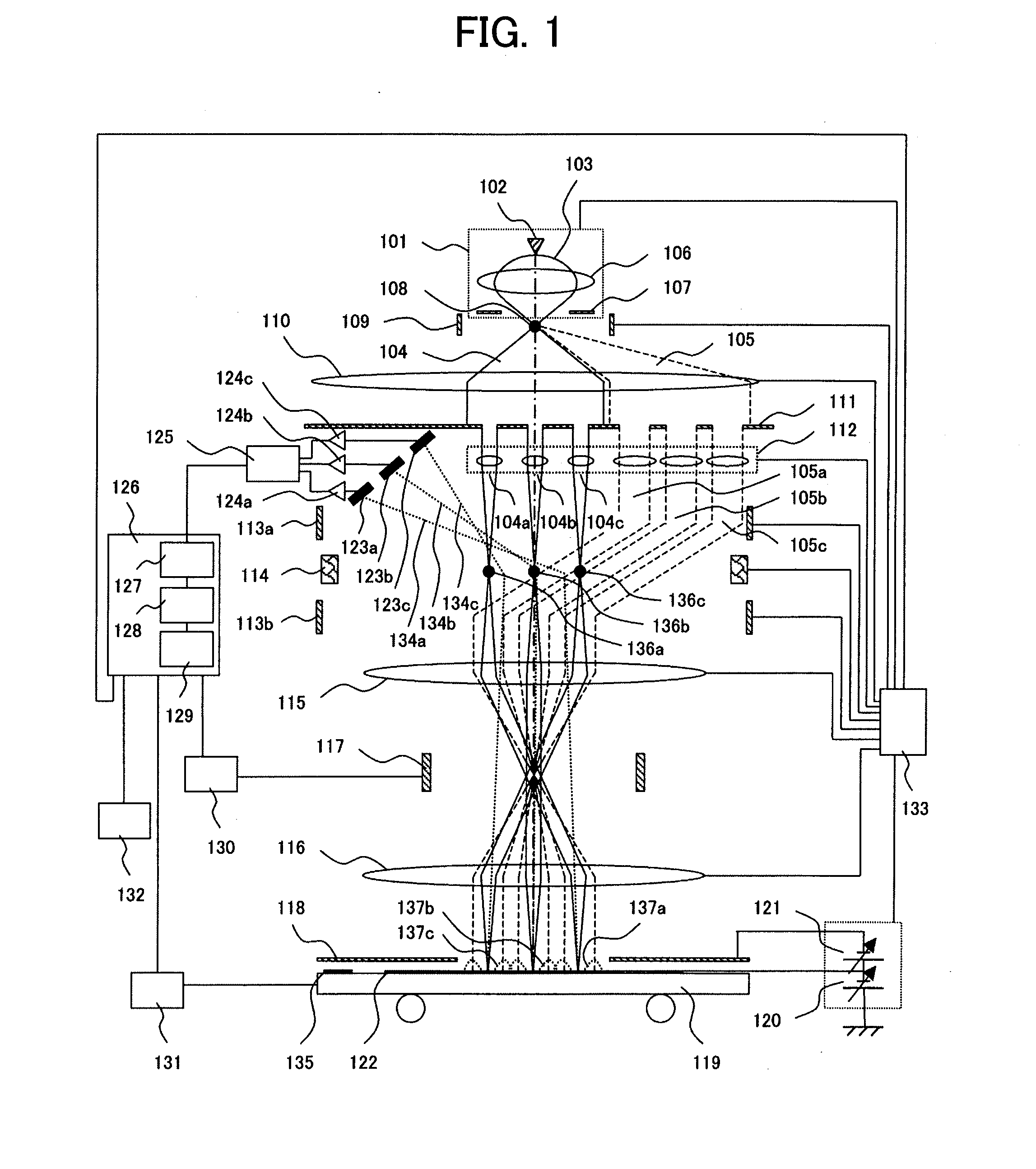
[0038]Described in the first embodiment is a multi-beam type scanning electron microscope including an aperture array and a lens array, both having multiple aperture patterns, further including a deflector that is disposed at the position of an electron source image above the aperture array and selects an aperture pattern, and changing the temporal timing between pre-charge and inspection. Thus configured apparatus realizes: with an easily-implementable configuration, change / switch of the timing between charge-control beam illumination and signal-detection beam illumination and reduction of time difference from the charge-control beam illumination to the signal-detection beam illumination to control charge and detect signals under optimal conditions, thereby improving defect detection sensitivity.
[0039]FIG. 1 is a schematic diagram of an electron beam inspection apparatus according to Embodiment 1. First of all, the configuration of the apparatus will be described. An electron gun 1...
embodiment 2
[0085]In Embodiment 1, switching between the illumination conditions of the charge-control beam and the illumination conditions of the signal-detection beam takes place in synchronization with scan signals to reduce the time difference from illumination by charge-control beams to illumination by signal-detection beams, thereby enabling an inspection with a wafer steadily charged. However, the embodiment may sometimes pose nonuniformity in image brightness and inspection sensitivity of every beam. To overcome the problem, the second embodiment provides an inspection method realizing uniform image brightness and inspection sensitivity.
[0086]First of all, the reason why the image brightness and inspection sensitivity of every beam become nonuniform in Embodiment 1 will be described with reference to FIGS. 7A, 7B and FIGS. 8A, 8B. FIG. 8A illustrates time variations of the amount of charge at a charge-control beam illuminated part. The amount of charge increased by a charge-control beam...
embodiment 3
[0090]In Embodiments 1 and 2, the conditions for the charge-control beams 702a to 702e and the conditions for the signal-detection beams 703a to 703e are switched over every time the beams sweep from one boundary to the other boundary of the beam illumination regions 701a to 701e; however, every switching operation of the illumination conditions takes a few seconds. The methods of Embodiments 1 and 2 that involve frequent switching of the illumination conditions may sometimes cause a long inspection time. If, however, the wafer 122 can hold the charge roughly equal to or longer than the time required to scan a stripe, it is enough to switch the conditions between charge-control beam illumination and signal-detection beam illumination every time one stripe is scanned. In the third embodiment, the above-described two conditions are switched every time one stripe is scanned. The third embodiment can reduce the number of times to switch the illumination conditions and reduce the duratio...
PUM
| Property | Measurement | Unit |
|---|---|---|
| time | aaaaa | aaaaa |
| surface electric field | aaaaa | aaaaa |
| surface electric-field | aaaaa | aaaaa |
Abstract
Description
Claims
Application Information
 - R&D
- Intellectual Property
- Life Sciences
- Materials
- Tech Scout
- Unparalleled Data Quality
- Higher Quality Content
- 60% Fewer Hallucinations
Browse by: Latest US Patents, China's latest patents, Technical Efficacy Thesaurus, Application Domain, Technology Topic, Popular Technical Reports.
© 2025 PatSnap. All rights reserved.Legal|Privacy policy|Modern Slavery Act Transparency Statement|Sitemap|About US| Contact US: help@patsnap.com


