
Liquid crystal display device and backlight control method

a liquid crystal display and backlight control technology, applied in the field of backlight control methods, can solve problems such as deterioration of image quality, drop in the brightness of a white background area surrounding the black window, and /b> becoming a problem, and achieve the effects of reducing electric power, improving image quality, and reducing power consumption

Active Publication Date: 2011-11-03
MAXELL HLDG LTD
View PDF4 Cites 23 Cited by
  • Summary
  • Abstract
  • Description
  • Claims
  • Application Information

AI Technical Summary

Benefits of technology

[0007]The aforementioned area control is capable of minimizing the power consumption of the entire backlight since the power consumption can be optimized for each of the areas. However, the execution of the area control can cause deterioration in the image quality depending on the pattern, design, etc. of the image displayed on the screen.
[0009]The screen 610 shown in FIG. 6 represents a case where a small white area (white window) 612 exists in a black background 611. By executing the area control in this case, the electric power (power consumption) can be reduced and the contrast can be improved. Specifically, with the increase in the black area in the screen, total reduction of the power consumption increases due to the increase in the number of areas undergoing the reduction of the backlight brightness. By the reduction of the backlight brightness of the black area 611, the so-called “black floating” (graying of black) is reduced and the contrast ratio between the white window 612 and the black area 611 is improved. On the other hand, the reduction of the backlight brightness of the black area 611 increases the possibility of a halo 613 developing around the white window 612 due to the leaking of the brightness of the white window 612 into the surrounding black area 611.
[0010]In contrast, the screen 620 shown in FIG. 6 represents a case where a small black area (black window) 622 exists in a white background 621. In this case, the aforementioned effects (power reduction and improvement of contrast) diminish since the number of areas undergoing the reduction of the backlight brightness is small and the visual contrast of the pattern (small black window 622 existing in the large white background 621) is already high. Further, a drop in the brightness of a white background area surrounding the black window 622 becomes a problem in this case since the reduction of the backlight brightness of the black window 622 eliminates light leaking from the black window area to the surrounding white background area. The brightness drop in a bright image significantly deteriorates the image quality in terms of visual perception.
[0012]It is therefore an object of the present invention to provide a liquid crystal display device and a backlight control method capable of achieving the electric power reduction and the image quality improvement in a well-balanced manner in the area control of the backlight.
[0016]By the present invention, a liquid crystal display device and a backlight control method capable of achieving the electric power reduction and the image quality improvement in a well-balanced manner in the area control of the backlight can be provided.

Problems solved by technology

However, the execution of the area control can cause deterioration in the image quality depending on the pattern, design, etc. of the image displayed on the screen.
Further, a drop in the brightness of a white background area surrounding the black window 622 becomes a problem in this case since the reduction of the backlight brightness of the black window 622 eliminates light leaking from the black window area to the surrounding white background area.
The brightness drop in a bright image significantly deteriorates the image quality in terms of visual perception.

Method used


Image

  • Liquid crystal display device and backlight control method
  • Liquid crystal display device and backlight control method
  • Liquid crystal display device and backlight control method

Examples


Embodiment Construction

[0026]Referring now to the drawings, a description will be given in detail of a preferred embodiment in accordance with the present invention. First, the configuration of backlight blocks, corresponding to “areas” of the backlight according to this embodiment, will be explained referring to FIGS. 7 and 8. Specifically, the backlight according to this embodiment is formed by arranging a plurality of backlight blocks in a two-dimensional array.

[0027]FIG. 7 is a schematic diagram showing an example of the configuration of the backlight block corresponding to each area of the backlight (i.e., corresponding to one of the 45 areas shown in FIG. 6, for example). As shown in FIG. 7, for example, each backlight block is equipped with a primary light source 901 (e.g., LED (Light-Emitting Diode)) mounted on a surface of an LED drive circuit board 902 facing a liquid crystal panel 906. On the other surface of the LED drive circuit board 902, an LED driver 907 for supplying driving current to th...


PUM


Abstract

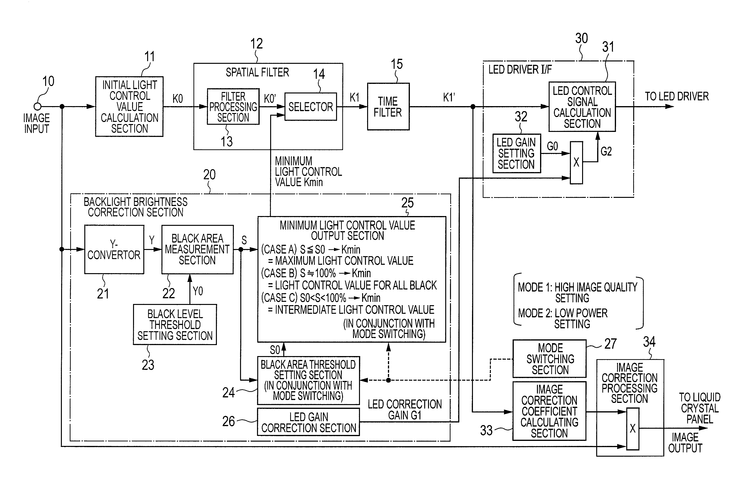
An initial light control value calculation section calculates the backlight's initial light control value K0 according to brightness of an inputted image signal for each area. A black area measurement section measures a black area S by obtaining ratio of the number of pixels satisfying Y≦Y0 (Y: brightness signal level, Y0: black level threshold) in the screen. A minimum light control value output section determines a minimum light control value Kmin based on comparison between the measured black area S and a black area threshold S0 and outputs a maximum value permissible for the light control value as the value Kmin when the black area S is the threshold value S0 or less. An LED control signal calculation section outputs a control signal to LED light sources based on a light control value K1 as the higher one of K0 and Kmin.

Description

CLAIM OF PRIORITY[0001]The present application claims priority from Japanese patent application serial No. JP 2010-103355, filed on Apr. 28, 2010, the content of which is hereby incorporated by reference into this application.BACKGROUND OF THE INVENTION[0002]1. Field of the Invention[0003]The present invention relates to a liquid crystal display device which includes a backlight for illuminating a liquid crystal panel (for displaying images) from behind and executes brightness adjustment of the backlight in response to an image signal inputted for the displaying of the images. The present invention relates also to a control method for the backlight.[0004]2. Description of the Related Art[0005]A liquid crystal display device is equipped with a non-emitting liquid crystal panel (light-transmissive optical modulation element) and a backlight arranged behind the liquid crystal panel to illuminate the panel with light, differently from self-emission display devices (CRT (Cathode Ray Tube...

Claims


Application Information

Patent Timeline
IPC IPC(8): G09G5/10
CPCG09G3/3426G09G2320/0233G09G2320/0238G09G2360/16G09G2320/0646G09G2320/0653G09G2320/0606
Inventor KURABAYASHI, HIROYUKITSURU, YASUTAKAOGI, YUYATANAKA, KAZUHIKOSHIRAISHI, AKIHIRO
Owner MAXELL HLDG LTD
Learn More