
Hybrid self-test circuit structure

a self-testing and circuit technology, applied in the direction of electronic circuit testing, measurement devices, instruments, etc., can solve the problems of increasing the wiring area, affecting the test results, and increasing the cost of the test, so as to reduce the wiring area required and minimize the testing cost of the test circui

Active Publication Date: 2011-11-03
ISTART TEK INC
View PDF7 Cites 2 Cited by
  • Summary
  • Abstract
  • Description
  • Claims
  • Application Information

AI Technical Summary

Benefits of technology

[0004]One objective of the present invention to provide a hybrid self-test circuit structure simultaneously having a parallel interface and a serial interface (or sequential interface) electrically coupled between n pieces of level functional units and provided for optimizing a circuit layout of a substrate, as well as providing a high efficiency of testing, diagnostic and repair for testing the memory units.
[0005]Another objective of the present invention is to provide a hybrid self-test circuit structure having a parallel interface, a serial interface or a daisy chair interface electrically coupled between n pieces of level functional units or functional units at the same level and provided for optimizing a circuit layout of a substrate, as well as providing a high efficiency of testing, diagnostic and repair for testing the memory unit.
[0006]A further objective of the present invention is to provide a hybrid self-test circuit structure, wherein n pieces of level functional units installed in the circuit structure are electrically coupled with each other by a parallel interface, a serial interface, a daisy chair interface, or a combination of any two or more of the above, and provided for optimizing a circuit layout of a substrate, as well as providing a high efficiency of testing, diagnostic and repair for testing the memory units.
[0008]Compared with the prior art, the hybrid self-test circuit structure of the present invention utilize a hybrid parallel interface and serial interface architecture for reducing the wiring area required for the circuit layout of the chip, providing a high-speed testing and diagnostic for testing the memory units, and diagnosing and repairing the memory units having an abnormal signal. The present invention further achieves the effect of minimizing the testing cost of the testing circuit of the memory units.

Problems solved by technology

If the quantity of testing memory units becomes larger, the control signal lines and the data bus lines will increase the wiring area greatly during a chip design process, and the increased wiring area will incur a higher cost, particularly for the advanced manufacturing process <65 nm, having a more significant increase of the wiring area and incurring a much higher cost.
In other words, the time and cost are increased, and such increase makes the self-test circuit unable to support the full-speed test function which is an important test for testing the fault coverage of the memory units.
If only the serial method is used for the testing, the issue of the wiring cost can be solved, but the memory units cannot be tested effectively.

Method used


Image

  • Hybrid self-test circuit structure
  • Hybrid self-test circuit structure
  • Hybrid self-test circuit structure

Examples


Embodiment Construction

[0019]The objects, characteristics and effects of the present invention will become apparent with the detailed description of preferred embodiments and the illustration of related drawings as follows.

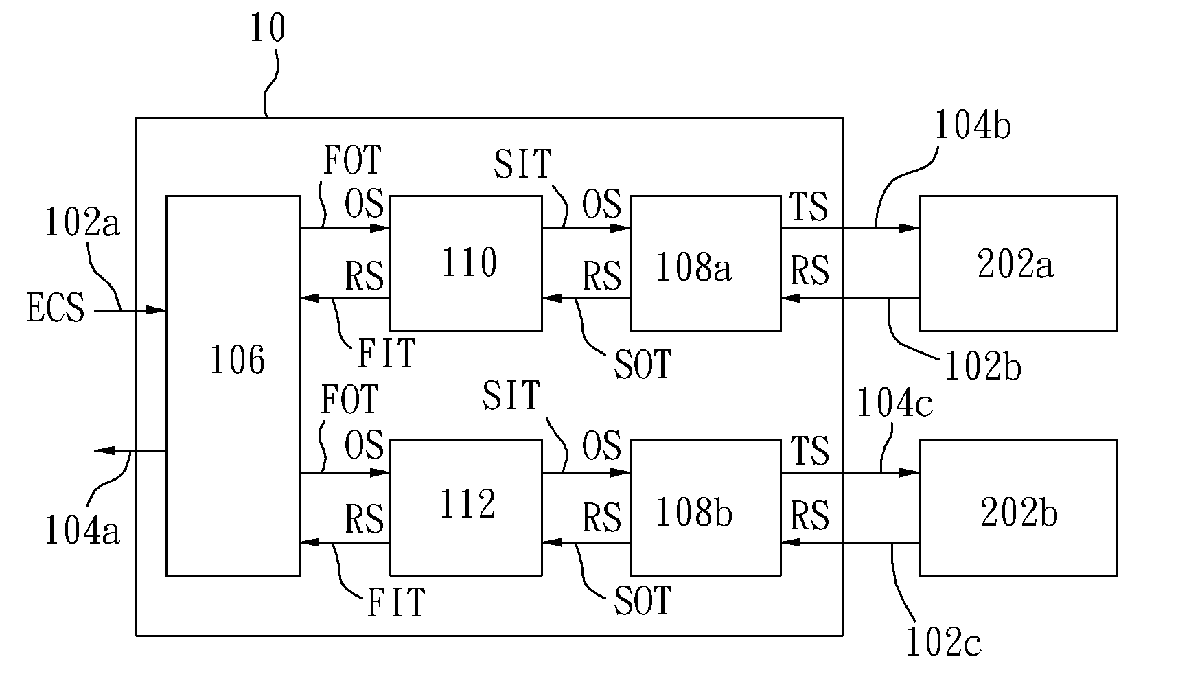
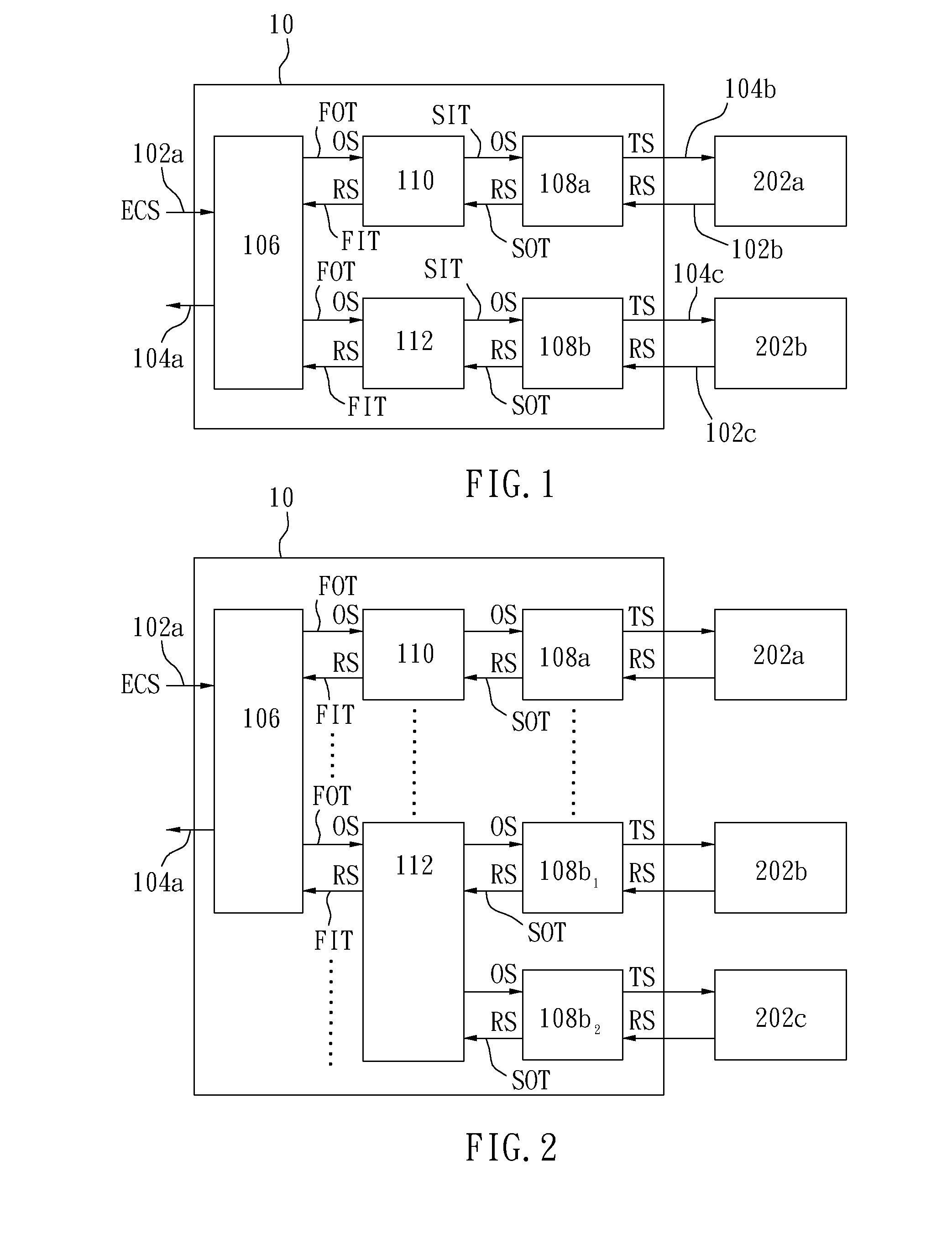
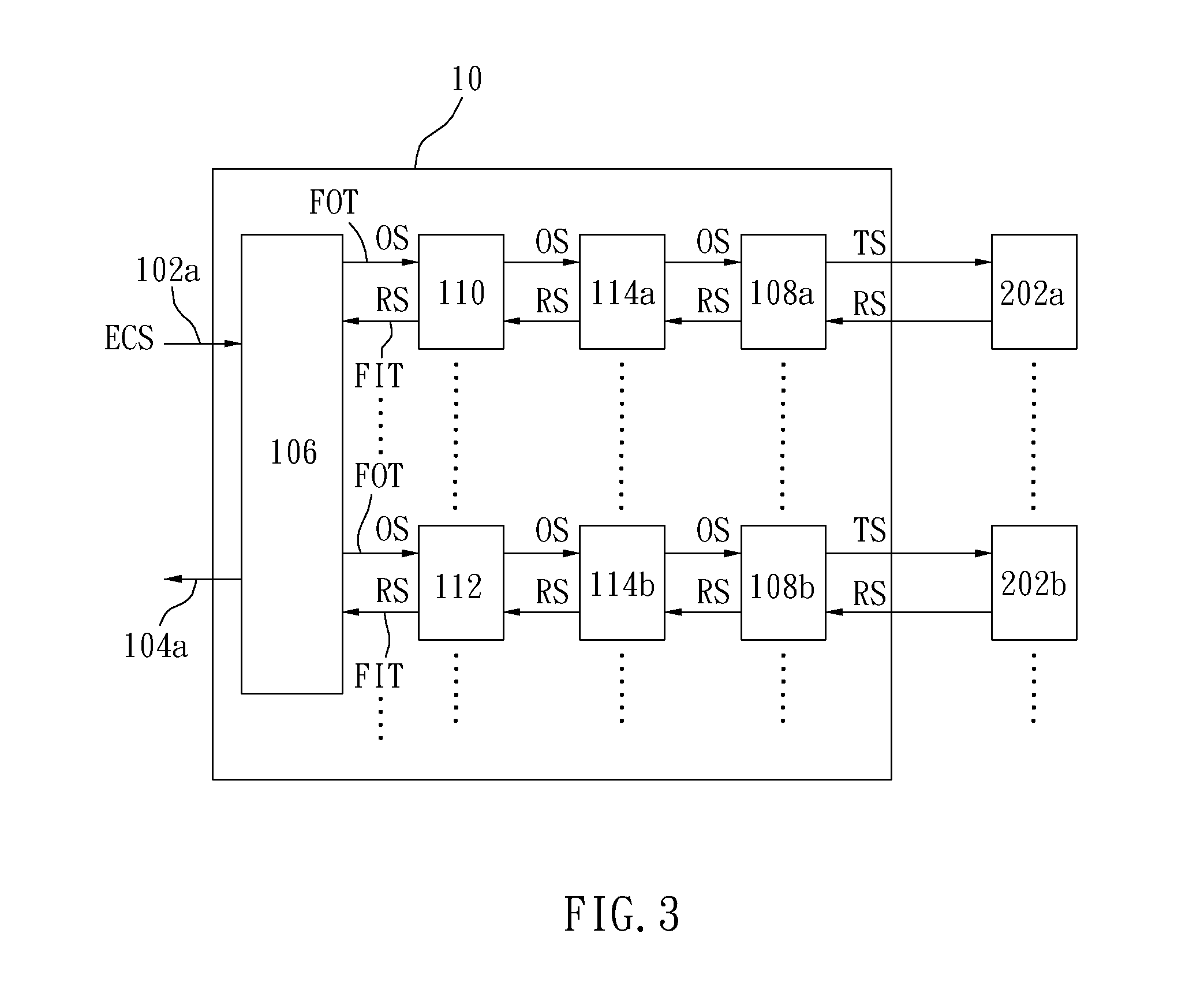
[0020]With reference to FIG. 1 for a schematic block diagram of a hybrid self-test circuit structure in accordance with a preferred embodiment of the present invention, the hybrid self-test circuit 10 comprises a plurality of input terminals 102a˜102c and a plurality of output terminals 104a˜104c for testing a plurality of memory units 202a, 202b. The hybrid self-test circuit 10 further comprises a first level functional unit 106, a plurality of second level functional units 108a, 108b, a parallel interface 110 and a serial interface 112. The first level functional unit 106 includes a first output terminal FOT, and the input terminal 102a is provided for receiving an external control signal ECS transmitted from the outside, and the first level functional unit 106 is provided for generat...


PUM


Abstract

A hybrid self-test circuit structure comprises a plurality of input terminals and a plurality of output terminals for testing a plurality of memory units. The circuit structure comprises a first level functional unit for driving a plurality of first output terminals electrically coupled to the first level functional unit to output an output signal according to an external control signal transmitted from the outside; a plurality of second level functional units for receiving the output signal and generating a test signal according to the output signal and outputting the test signal to the memory units; a parallel interface parallelly installed between the first level functional unit and at least one of the second level functional units; and a serial interface serially installed between the first level functional unit and at least one of the second level functional units.

Description

FIELD OF THE INVENTION[0001]The present invention relates to a self-test circuit structure of a memory unit, in particular to a hybrid self-test circuit structure having a parallel interface and a serial interface electrically coupled to a plurality of level functional units.BACKGROUND OF THE INVENTION[0002]Conventionally, embedded self-test circuit architecture is adopted for testing memory units, wherein a large quantity of control signal lines and data bus lines are used for transmitting signals, issuing instructions or performing operations. Although the aforementioned parallel architecture can achieve the effect of sending out an access instruction in every clock cycle to perform an full-speed test to the memory units. If the quantity of testing memory units becomes larger, the control signal lines and the data bus lines will increase the wiring area greatly during a chip design process, and the increased wiring area will incur a higher cost, particularly for the advanced manuf...

Claims


Application Information

Patent Timeline
Patent Type & Authority Applications(United States)
IPC IPC(8): G01R31/02
CPCG11C29/1201G11C2029/0401G11C29/48G11C29/26
Inventor HSING, YU-TSAOTENG, LI-MING
Owner ISTART TEK INC
Learn More