
Wireless communication apparatus, wireless communication system and wireless communication method

a wireless communication system and wireless communication technology, applied in the field of wireless communication apparatus, can solve the problems of inability to predict the ideal xpd, the influence of the polarized wave gain, and the correlation between the elements of the channel matrix, so as to achieve effective precoding and lessen the interference between different polarized waves

Active Publication Date: 2011-10-27
SUN PATENT TRUST
View PDF2 Cites 75 Cited by
  • Summary
  • Abstract
  • Description
  • Claims
  • Application Information

AI Technical Summary

Benefits of technology

[0024]Even when a MIMO system using a cross-polarized antenna structure cannot accomplish ideal XPD, the present invention makes it possible to lessen interference between different polarized waves and perform effective precoding.

Problems solved by technology

If cross-polarized antennas assigned different polarized waves are used respectively for a transmitter and a receiver, an imbalance will occur in gains (or power) of and correlation among elements of a channel matrix.
As a consequence, the elements of the channel matrix exhibit more complex behaviors.
However, in order to lessen complexity of implementation and retain one code book intended for all applications (various antenna structures), the current LTE includes no code book specifically designed for the cross-polarized antenna structure.
In general, however, ideal XPD cannot always be expected.
Therefore, when conditions for ideal XPD are not satisfied, precoding performance is deteriorated.

Method used


Image

  • Wireless communication apparatus, wireless communication system and wireless communication method
  • Wireless communication apparatus, wireless communication system and wireless communication method
  • Wireless communication apparatus, wireless communication system and wireless communication method

Examples


first embodiment

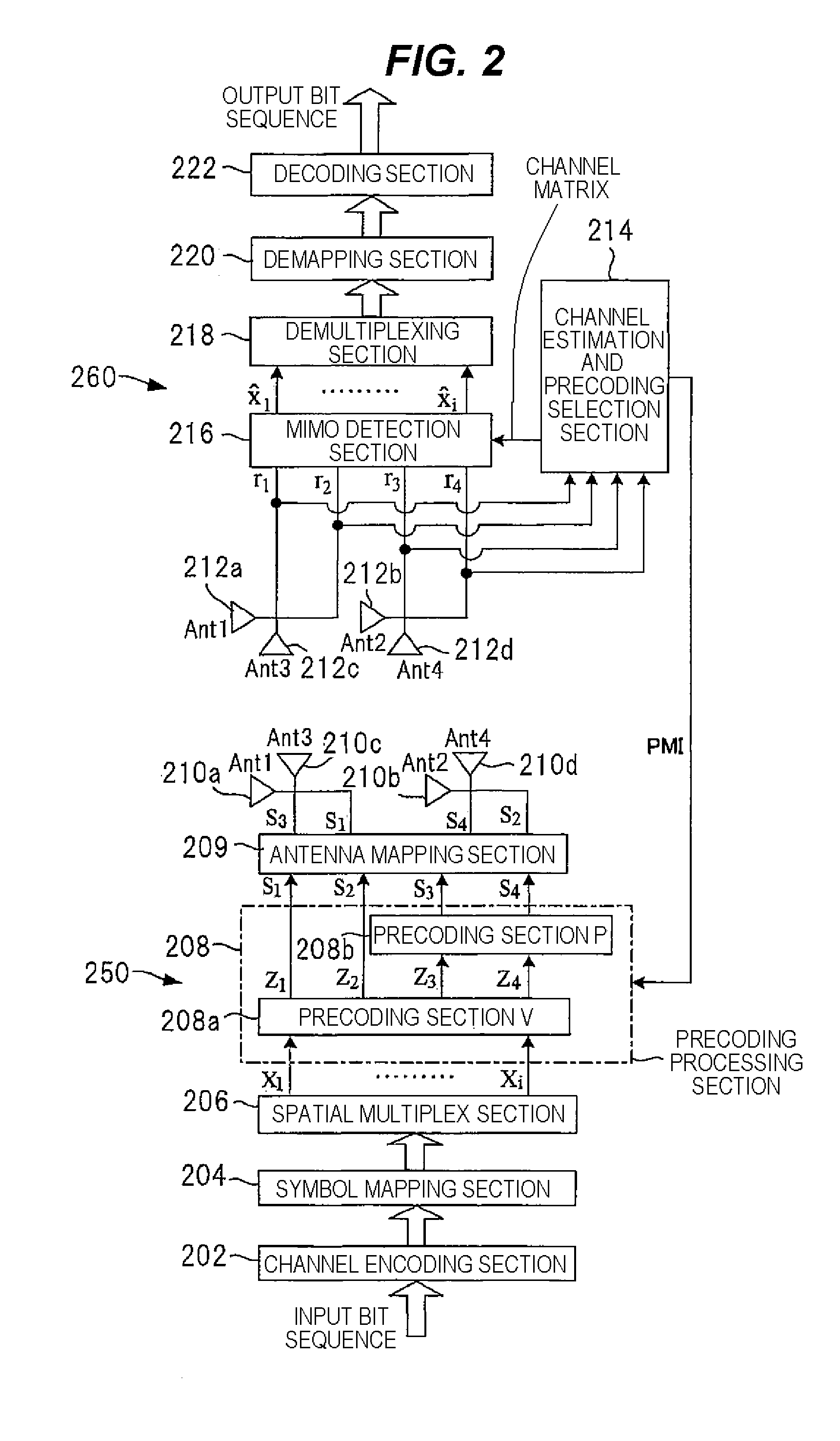
[0062]FIG. 2 is a block diagram showing a first example configuration of a wireless communication system using a cellular wireless communication network as a first embodiment of the present invention. The first embodiment shows an example configuration achieved when a transmitter and a receiver each have a plurality of (four in the embodiment) cross-polarized antennas and transmit a plurality of data streams X1 to Xi. A wireless communication system exemplified herein uses a transmitter BS and a receiver UE and establishes a downlink communication between one transmitter and one receiver by means of a MIMO technique. The number of antennas is not limited to four, and a plurality of antennas can be set as required.

[0063]The cross-polarized MIMO system of the first embodiment has a transmitter 250 serving as BS and a receiver 260 serving as UE. The transmitter 250 transmits a spatially multiplexed data stream to the receiver 260 by way of a MIMO channel by means of MIMO communication....

second embodiment

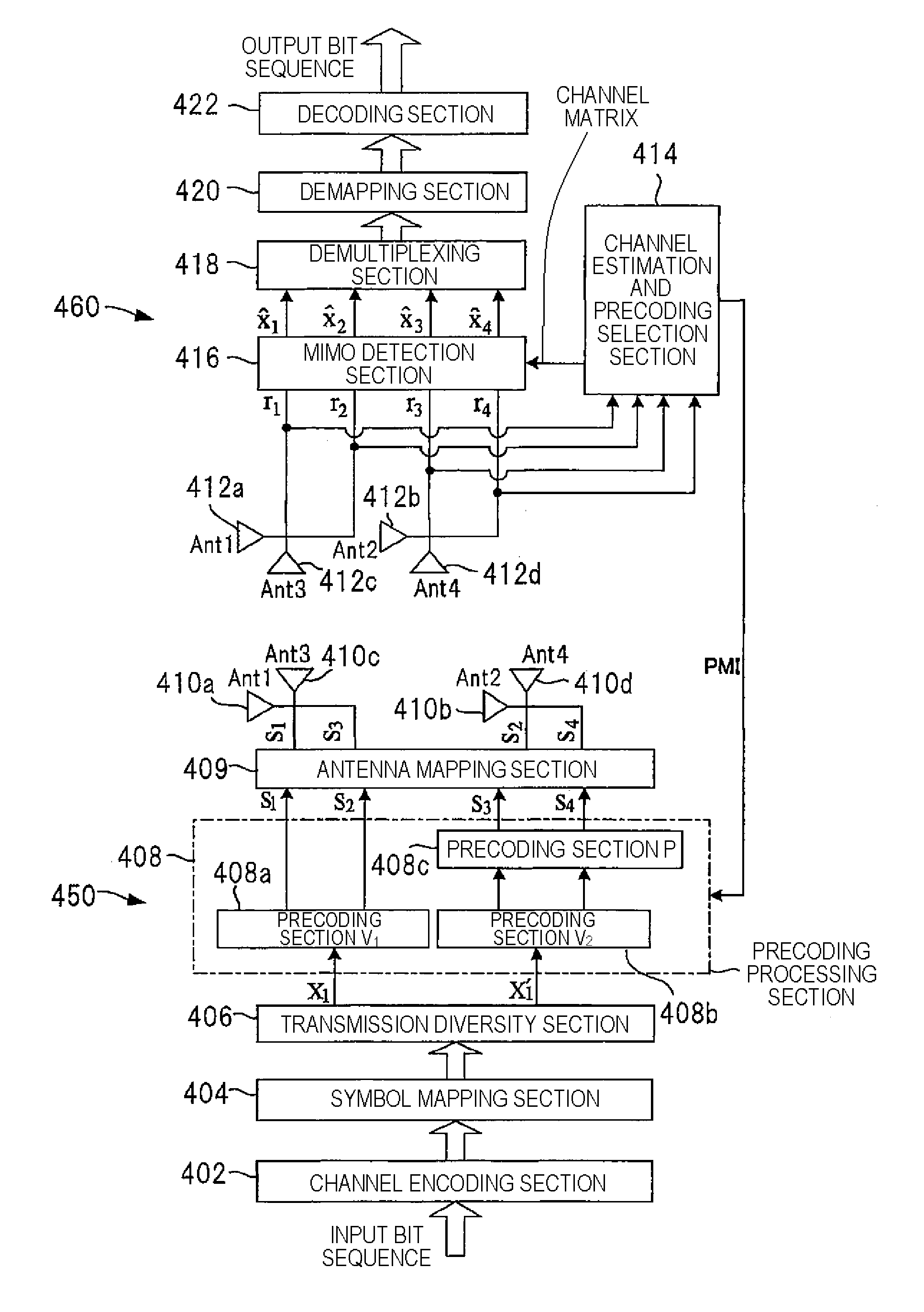
[0087]FIG. 4 is a block diagram showing, as a second embodiment of the present invention, a second example configuration of the wireless communication system using the cellular wireless communication network. The second embodiment is an example configuration taking into consideration a rank-1 transmission (the number of transmission streams is one) performed in the 4-by-4 cross-polarized MIMO system. A transmitter 450 has four transmission antennas 410a to 410d (Ant1 to 4) each of which has a cross-polarized structure, and the receiver 460 has four reception antennas 412a to 412d (Ant1 to 4) each of which has a cross-polarized configuration. A spatially multiplexed data stream is transmitted from the transmitter 450 to the receiver 460 by means of MIMO transmission and by way of a MIMO channel.

[0088]The transmitter 450 includes a channel encoding section 402, a symbol mapping section 404, a transmission diversity section 406, a precoding processing section 408, and an antenna mappin...

third embodiment

[0095]FIG. 5 is a block diagram showing, as a third embodiment of the present invention, a third example configuration of the wireless communication system using the cellular wireless communication network. The third embodiment is an example configuration taking into account rank-2 transmission (the number of transmission streams is two) in the 4-by-4 cross-polarized MIMO system. A transmitter 550 has four transmission antennas 510a to 510d (Ant1 to 4) each of which has a cross-polarized configuration. A receiver 560 has four reception antennas 512a to 512d (Ant1 to 4) each of which has a cross-polarized configuration. A spatially multiplexed data stream is transmitted from the transmitter 550 to the receiver 560 by means of MIMO communication and by way of a VIIMO channel.

[0096]The transmitter 550 has a channel encoding section 502, a symbol mapping section 504, a spatial multiplexing section 506, a precoding processing section 508, and an antenna mapping section 509. The precoding...


PUM


Abstract

In a MIMO system using a cross-polarized antenna structure, even if no ideal XPD can be obtained, the interference between different polarized waves can be reduced to allow an effective precoding to be executed. When a MIMO communication is performed between a transmitter (250) and a receiver (260) each using a cross-polarized antenna structure, a channel estimating and precoding selection section (214) of the receiver (260) performs a channel estimation of MIMO channels from the transmitter to the receiver, decides a precoding matrix (P) of a projection matrix for mutually orthogonalizing or substantially orthogonalizing the channel response matrixes for respective different polarized waves, and feeds the determined precoding matrix (P) back to the transmitter (250). In the transmitter (250), a precoding processing section (208) applies the precoding matrix (P) to the spatial stream corresponding to one of the polarized waves to perform a precoding, thereby allowing the transmitter (250) to transmit the polarized waves with the orthogonality therebetween maintained.

Description

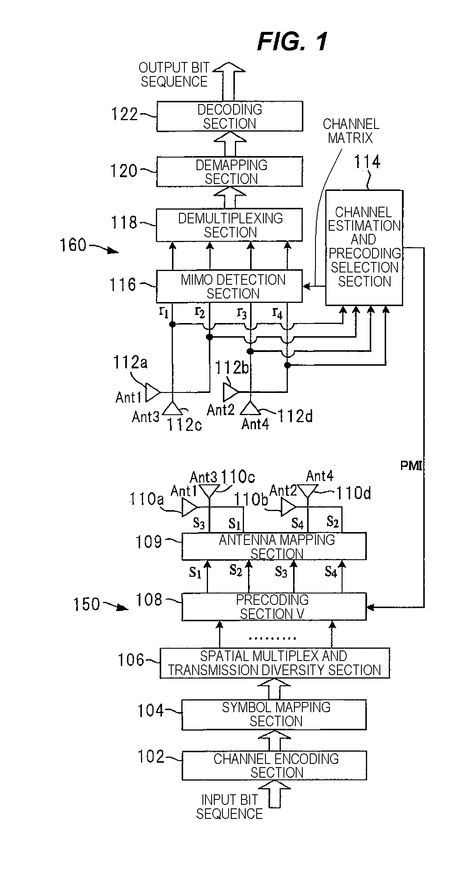
TECHNICAL FIELD[0001]The present invention relates to a wireless communication apparatus, a wireless communication system and a wireless communication method used in a MIMO (Multiple Input Multiple Output) system that conducts communication by use of a plurality of antennas.BACKGROUND ART[0002]The MIMO system is a communication system using a plurality of transmission antennas and a plurality of reception antennas for data communication. An access point to which a user terminal is connected can conduct communication with one user terminal or more at an arbitrary required point in time over a downlink and an uplink. The downlink (i.e., a forward link) is a communication link originating from the access point to the user terminal, whilst the uplink (i.e., a backward link) is a communication link originating from the user terminal to the access point.[0003]The access point is usually a wireless communication device realized by a stationary base station that establishes communication wi...

Claims


Application Information

Patent Timeline
Patent Type & Authority Applications(United States)
IPC IPC(8): H04B7/02H04L25/03
CPCH04L2025/03808H04B7/0413H04B7/0639H04B7/10H04L25/0224H04L25/0248H04B7/0456H04L25/03961H04B7/0469H04B7/0691H04B7/002H04B7/0617H04B7/0634H04L25/03898
Inventor YU, QIANHUANG, LEIHOSHINO, MASAYUKIIMAMURA, DAICHI
Owner SUN PATENT TRUST
Learn More