


Quick Research
Generate reliable direction feasibility study reports for your R&D in just a few steps.

Technical Q&A
Discover and master advanced knowledge NOW. Basics, ideas, possibilities, all at once.

Find Solutions
As an expert in R&D theories, this can generate solutions to your technical problems instantly.

Evaluate Feasibility
Analyze your overall solution with one click, know your potential R&D risks in advance.

Monitor Landscape
Get weekly tech updates, stay abreast of the latest tech innovations and key insights.
Physical section of atomic oscillator
a technology of atomic oscillators and atomic resonances, applied in the field of physical sections of atomic oscillators, can solve the problems of atomic oscillator downsizing, and affecting the operation of the instrument. , to achieve the effect of stabilizing characteristics, preventing overheating of the light source, and high accuracy and downsizing
- Summary
- Abstract
- Description
- Claims
- Application Information
AI Technical Summary
Benefits of technology
Problems solved by technology
Method used
Image

Examples
first modification
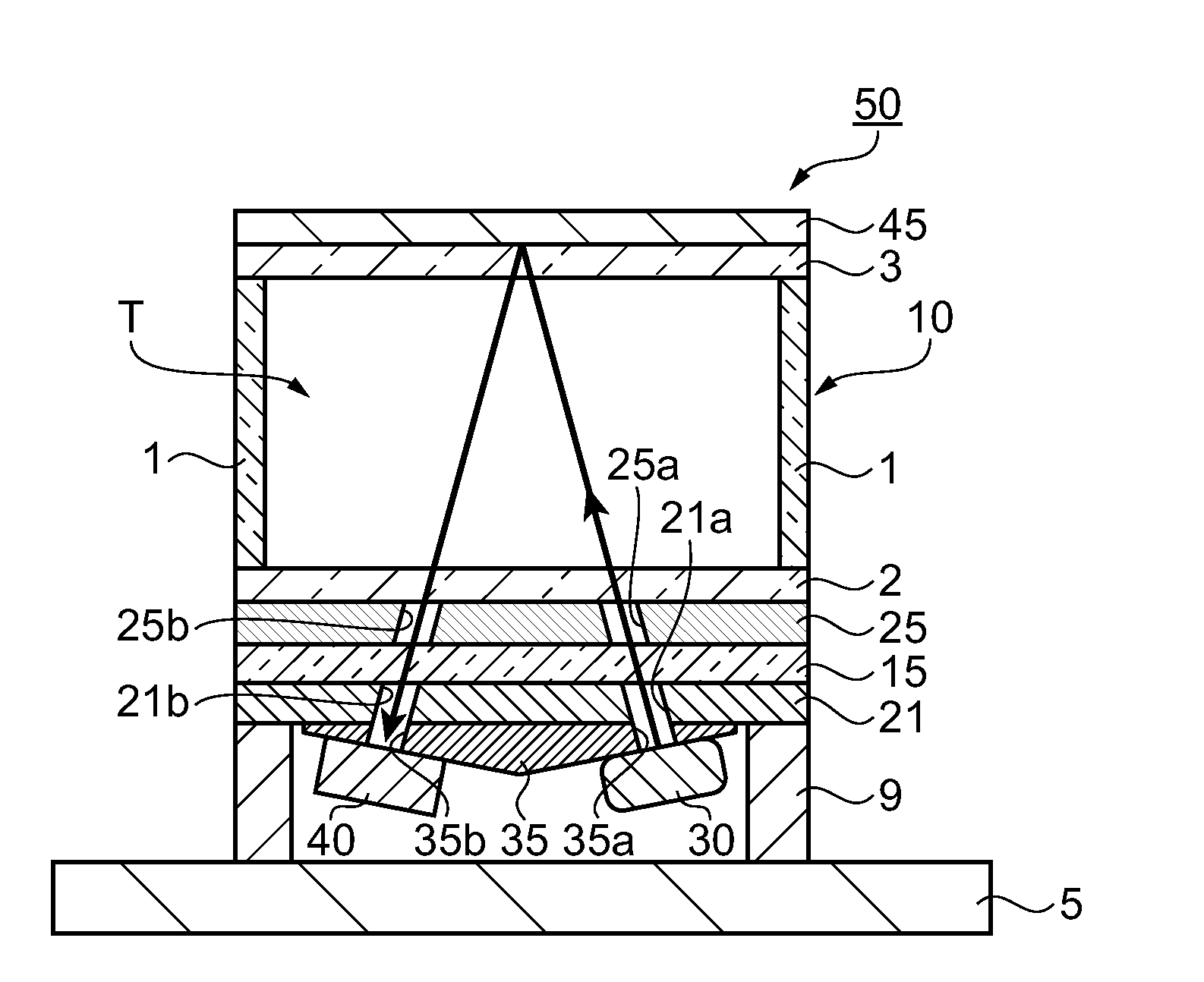
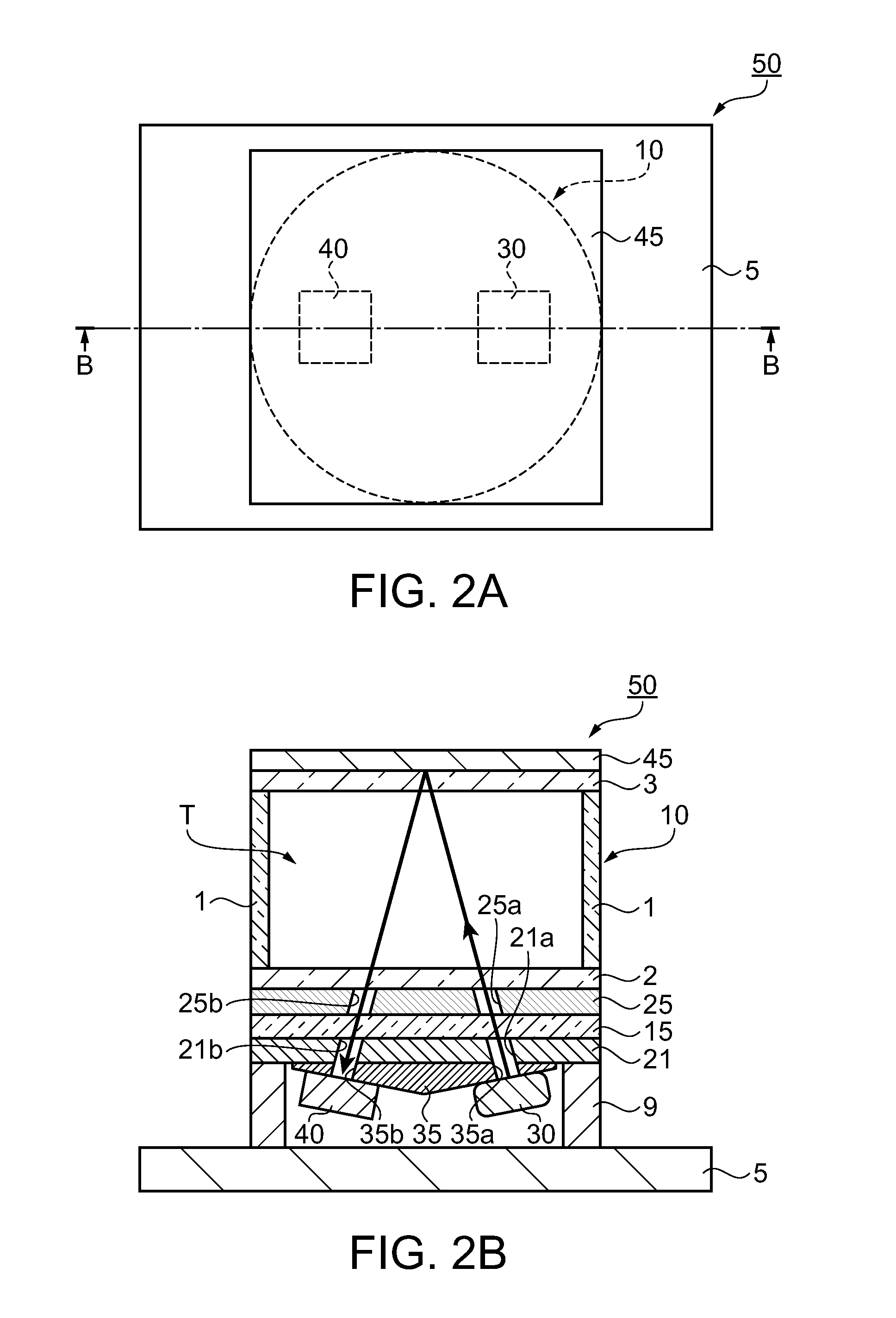
[0054]In the above embodiment, the VCSEL 30 and the photo sensor 40 are disposed on the inclined surfaces of the inclination member 35. In addition, the inclination angle of the inclined surfaces on which the VCSEL 30 and the photo sensor 40 are disposed is set such that the excitation light emitted from the VCSEL 30 is reflected by the light reflection film 45 and made incident on the photo sensor 40. However, the structure is not limited to this. Such structure that a reflection angle of the excitation light is adjusted by using a plurality of light reflection planes enables arrangement of the VCSEL 30 and the photo sensor 40 on a single plane without using the inclination member.
[0055]FIG. 4 is a sectional view for schematically explaining a physical section of an atomic oscillator using a light reflection section having two light reflection planes. The elements of the atomic oscillator of a first modification that are identical to those of the atomic oscillator of the above embo...
second modification
[0061]In the above embodiment and the first modification, the through holes 25a and 25b or the through holes 125a and 125b are formed on the regions, to be the optical path of the excitation light, of the heater 25 or the heater 125 which is one of members having no optical transparency. However, through holes need not be formed by using a heater material having optical transparency.
[0062]FIGS. 5 and 6 are sectional views for schematically explaining a physical section of an atomic oscillator provided with a heater made of a transparent electrode film. FIG. 5 shows a structure using a heater made of a transparent electrode film in the physical section 50 of the atomic oscillator of the above embodiment. FIG. 6 shows a structure using a heater made of a transparent electrode film in the physical section 150 of the atomic oscillator of the first modification. The elements of the atomic oscillator of the present modification (a second modification) that are identical to those of the at...
PUM
 Abstract
Description
Claims
Application Information
 - R&D Engineer
- R&D Manager
- IP Professional
- Industry Leading Data Capabilities
- Powerful AI technology
- Patent DNA Extraction
Browse by: Latest US Patents, China's latest patents, Technical Efficacy Thesaurus, Application Domain, Technology Topic, Popular Technical Reports.
© 2024 PatSnap. All rights reserved.Legal|Privacy policy|Modern Slavery Act Transparency Statement|Sitemap|About US| Contact US: help@patsnap.com