Internal Microphone Support System for Percussion Instruments

a technology for percussion instruments and microphones, applied in the field of percussion instrument internal microphone stands and isolation means, can solve the problems of insufficient isolation of recording means, difficult to capture sound from these types of percussion instruments, and the nature of the instrument introduces considerable vibration and reverb, and achieves the effect of increasing modularity

Active Publication Date: 2011-10-27
MOLLICK JONATHAN
View PDF1 Cites 8 Cited by
  • Summary
  • Abstract
  • Description
  • Claims
  • Application Information

AI Technical Summary

Benefits of technology

[0014]Another object of the present invention is to provide a device that isolates vibration and reverberation of a microphone within the interior of a drum cavity. The material of the frames provides vibration attenuation and damping, decou...

Problems solved by technology

Capturing sound from these types of percussion instruments can be a difficult task.
The nature of the instrument introduces considerable vibration and reverberation that may interfere with the recording process.
Percussionists, audio technicians and engineers have tried several means for recording percussion instruments while eliminating the resonating components during performances and studio sessions, but most share a common drawback of not properly isolating the recording means.
Those that incorporate isolation tend to ignore modularity in the support structure, which provides multiple configurations with regard to microphone positioning and the type of microphone being supported.
Typically microphones are rigidly mounted within the cavity of a drum or supported in a static configuration that is difficult to change or adapt if an unwanted sound or secondary noise source is disrupting the sound being recorded....

Method used


Image

  • Internal Microphone Support System for Percussion Instruments
  • Internal Microphone Support System for Percussion Instruments
  • Internal Microphone Support System for Percussion Instruments

Examples


Embodiment Construction

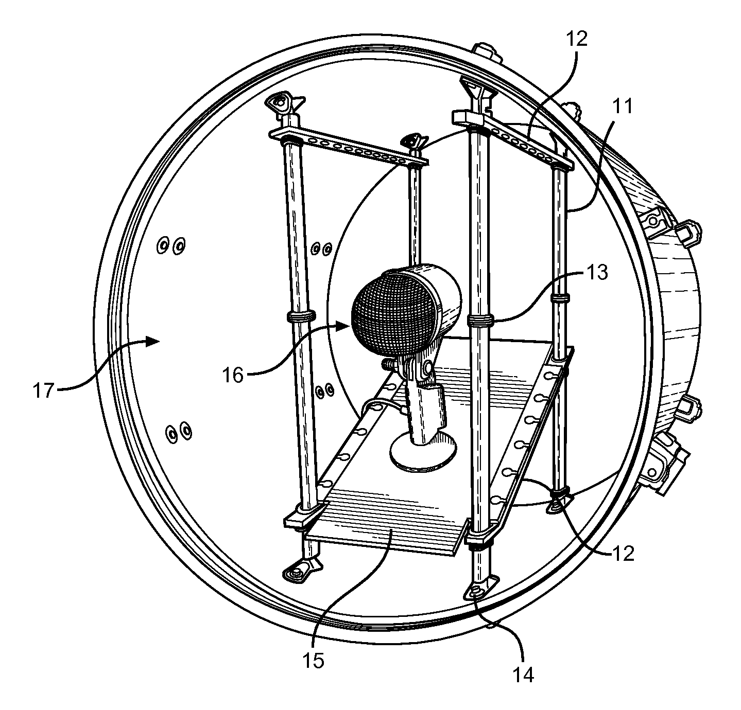
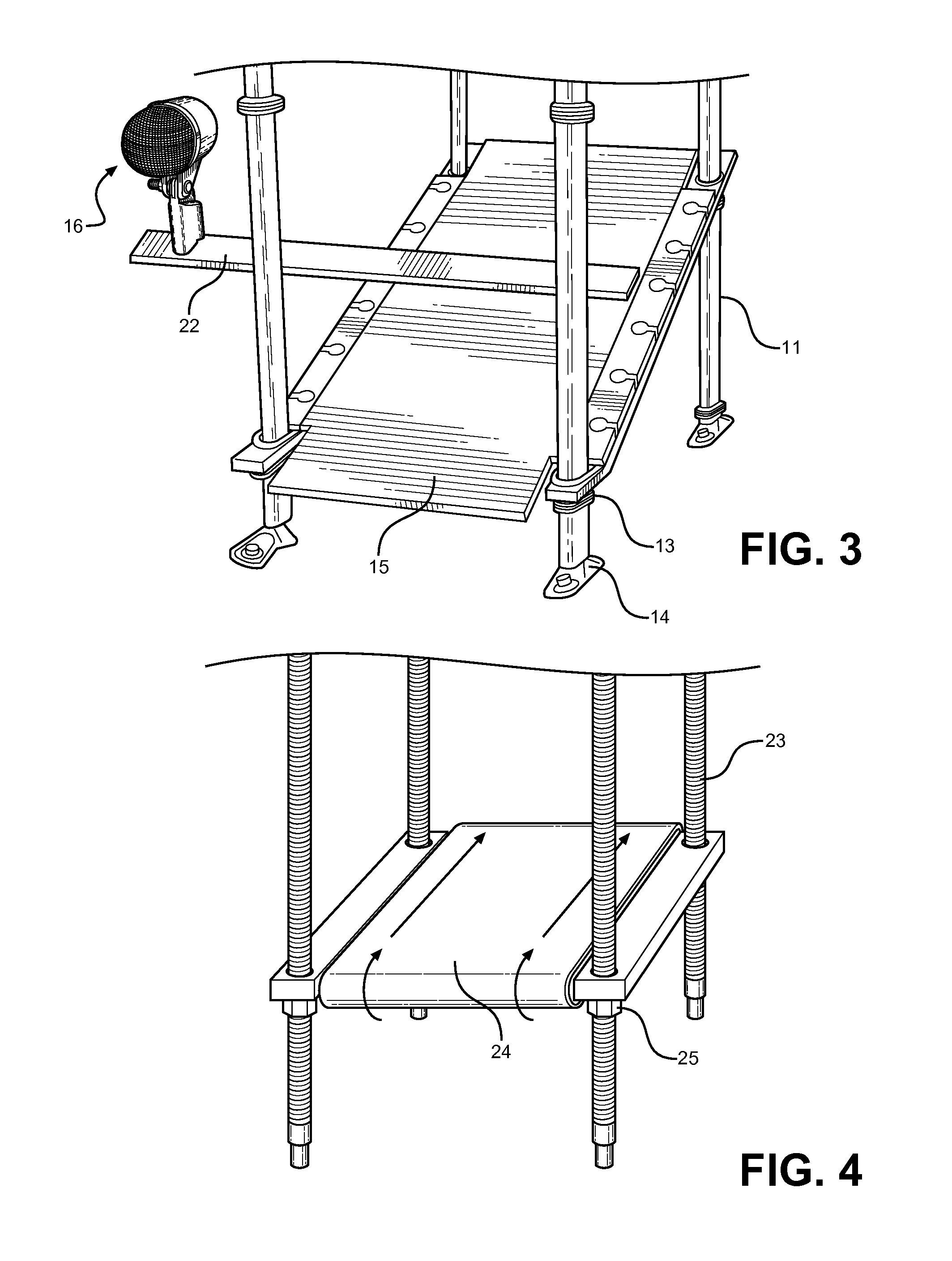
[0025]Referring now to FIG. 1, there is shown a perspective view of the preferred embodiment of the present invention. Four vertical straps 11 are situated within the interior of a drum 17 cavity. The straps 11 terminate at the drum shell interior surface and attach thereto via a drum shell lug 14. Horizontal straps 12 span two sets of vertical straps 11 to create opposing H-frames, which support various devices that secure to and position a microphone 16 for sound recording purposes. In the preferred embodiment, a flat plane 15 is provided that spans the internal gap between the four vertical straps 11 and attaches thereto at its corners. O-ring grommets 13 are provided along the length of the vertical straps to support the flat plane 15 in a given position and prevent its sliding along the straps 11. The internal friction between the vertical straps 11 and the horizontal straps 12 are sufficient to secure its position, but the grommets 13 provide additional support, especially in ...


PUM


Abstract

An internal support device comprising horizontal and vertical straps and a plurality of mounting devices for positioning and isolating acoustic microphones interior to a percussion instrument. The vertical straps are rubber or similar shock absorbing material, arranged in a rectangular pattern and secured at their ends to a percussion instrument shell using a series of isolating lug attachments. Horizontal straps of similar material span opposing vertical straps to form two H-shaped frames for one or a plurality of microphone stand devices. Embodiments of the stand devices include a flat plane attached between the vertical straps, a modified flat plate with an internal wire harness for suspending a microphone, and a flat plane with microphone arm extensions therefrom. An alternate embodiment of the overall device includes a motorized adjustment means and a conveyor means for positioning and refining a microphone position within the drum interior without entering the drum cavity. The disclosed invention provides for modular placement and support for different types of microphones within a percussion instrument, as well as improved microphone isolation for better sound quality in a sound studio or recording environment.

Description

CROSS REFERENCE TO RELATED APPLICATION[0001]This application claims the benefit of U.S. Provisional Application No. 61 / 326,819 filed on Apr. 22, 2010, entitled “2 “H” Elevation.”BACKGROUND OF THE INVENTION[0002]1. Field of the Invention[0003]The present invention relates to acoustic microphone support devices. More specifically, the present invention pertains to percussion instrument internal microphone stands and isolation means.[0004]2. Description of the Prior Art[0005]Percussion instruments include a family of instruments that produce sounds when struck, shaken or rubbed with a secondary object. The sound is produced by the vibration of instrument and interaction with surrounding air after initial perturbation. Included in this family of instruments are drums, including drum kits that utilize an array of drum designs to create different frequency sounds. The drum types that pertain to the present invention include those with a rigid outer shell and a sufficient internal cavity t...

Claims


Application Information

Patent Timeline
IPC IPC(8): G10D13/02
CPCH04R1/08G10D13/02
Inventor MOLLICK, JONATHAN
Owner MOLLICK JONATHAN
Why Eureka
Try Eureka