Thermal insulation containing supplemental infrared radiation absorbing material
a technology of infrared radiation and absorbing material, which is applied in the field of thermal insulation, can solve the problems of surface reduction of convection as heat transport mechanism, achieve the effect of reducing radiative heat loss, improving overall extinction efficiency, and improving effective wavelength rang
- Summary
- Abstract
- Description
- Claims
- Application Information
AI Technical Summary
Benefits of technology
Problems solved by technology
Method used
Image
Examples
example 1
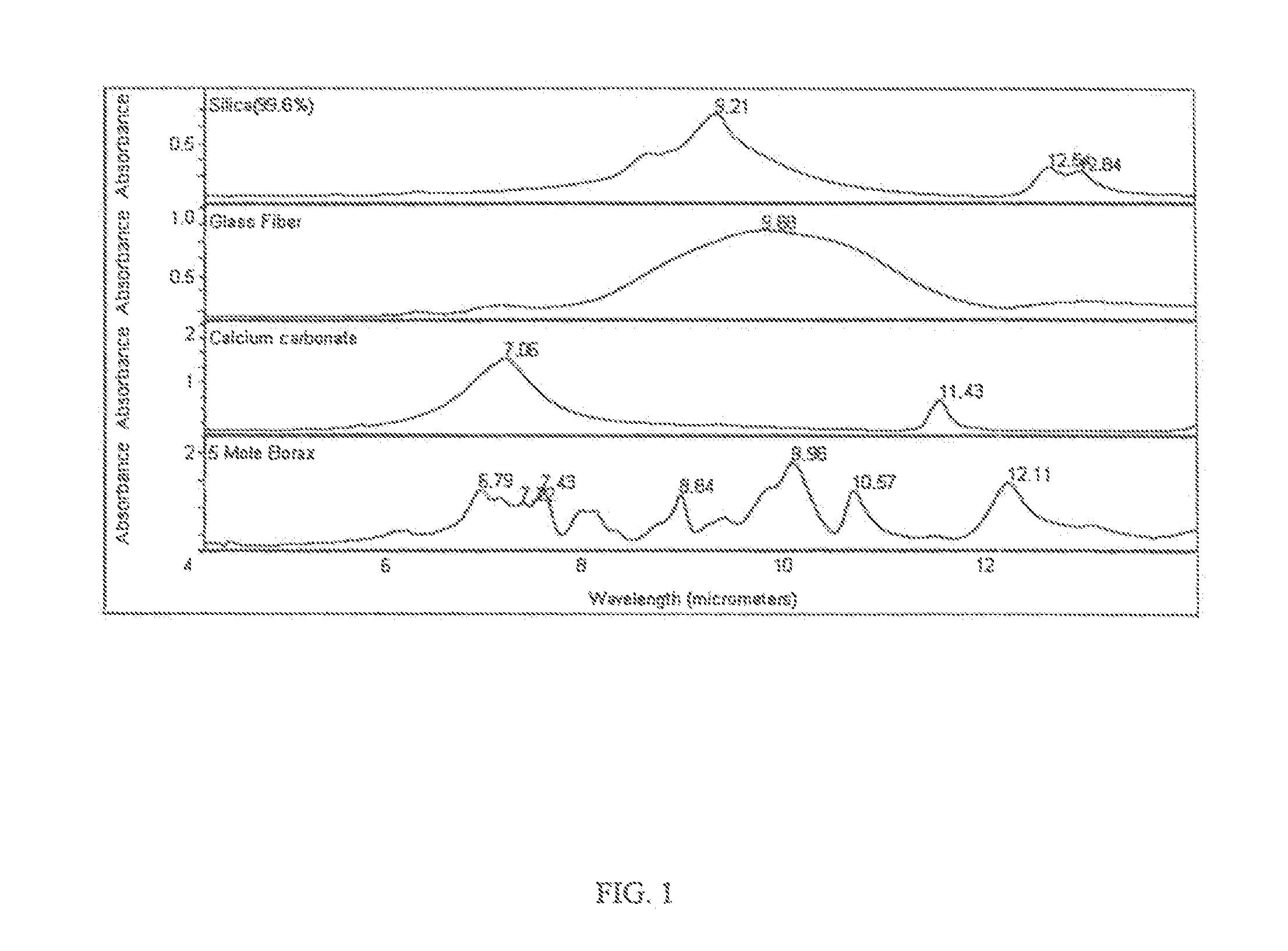
[0035]FIBERGLASS samples are prepared in a laboratory with either borax {Na2B4O7.10H2O} or calcium carbonate dispersed throughout as IR absorbing and scattering materials. The samples are 30.5 cm wide×30.5 cm long×2.5 cm thick. The IR absorbing materials are weighed and mixed in a solution of 30% isopropanol and 70% water. The borax is dissolved in the water using a mixer and a hot plate to form a borax solution. The calcium carbonate is mixed in the alcohol / water by hand to form a calcium carbonate suspension. The liquid mixtures containing the IR absorbing and scattering material are loaded onto the samples either by soaking or by spraying. The soaking is performed by pouring 240 ml of one of the liquid mixtures onto each sample and soaking the sample. The spraying is performed by using a spray bottle to spray 120 ml of one of the liquid mixtures onto each sample. The apparent thermal conductivity of each of the samples is measured before and after the IR absorbing material is add...
example 2
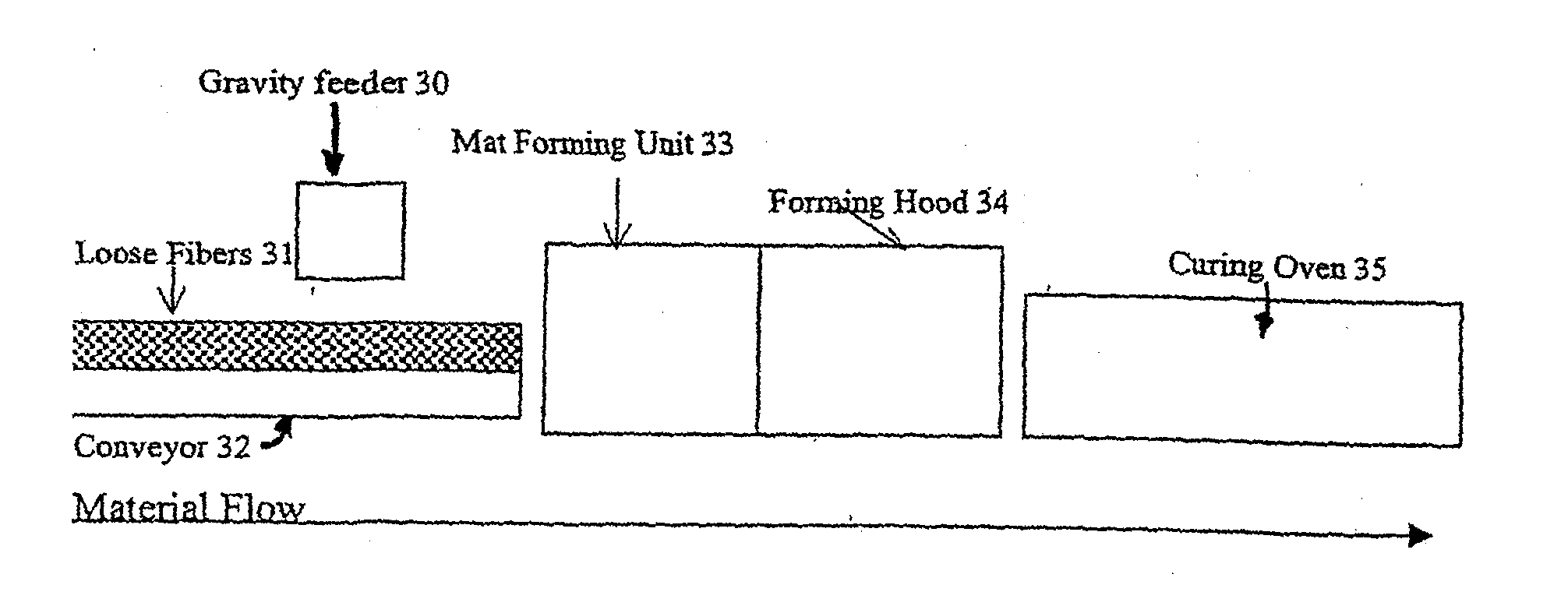
[0038]Two sets of FIBERGLASS samples of varying compositions in a fiberglass insulation manufacturing process are prepared. The first set of samples is maintained as a reference. To the second set of samples is added 12 wt % calcium carbonate. The apparent thermal conductivity at 24° C. mean temperature of each sample as a function of density is determined by ASTM test procedure C518 and shown in Table 4.
TABLE 3Fiber-Apparent thermalApparent thermalglassconductivity**conductivity** standardDensitystandardproduct withkg / m3product12 wt % CaCO38.0147.4148.098.9745.1645.7511.241.4141.9012.639.8340.2612.839.5739.9914.438.1838.56**Thermal conductivity units = (mW / m ·° C.) tested by ASTM C518 test method at 24° C. mean temperature
[0039]Using the data in Table 3, the reduction in apparent thermal conductivity resulting from the addition of calcium carbonate is compared with the reduction in apparent thermal conductivity resulting from an increase in glass density in the FIBERGLASS insulatio...
example 3
[0042]A fiberglass insulation sample with 12 wt % calcium carbonate is prepared in a fiberglass manufacturing process. Table 5 shows the reduction in apparent thermal conductivity at various temperatures compared to a fiberglass insulation sample with no calcium carbonate.
TABLE 5Apparent thermalReduction in apparentconductivity**Reduction in apparentthermal conductivity**test temperaturethermal conductivity**by CaCO3 compared to a(product density =from 12 wt %12 wt % weight increase24 kg / m3)addition of CaCO3with glass fiber10° C.0.6%24%50° C.4.6%132%400° C. 19.2%233%**Thermal conductivity units = (mW / m ·° C.) tested by ASTM C518 test method.
PUM
| Property | Measurement | Unit |
|---|---|---|
| particle size | aaaaa | aaaaa |
| wavelength | aaaaa | aaaaa |
| wavelength | aaaaa | aaaaa |
Abstract
Description
Claims
Application Information
 - R&D
- Intellectual Property
- Life Sciences
- Materials
- Tech Scout
- Unparalleled Data Quality
- Higher Quality Content
- 60% Fewer Hallucinations
Browse by: Latest US Patents, China's latest patents, Technical Efficacy Thesaurus, Application Domain, Technology Topic, Popular Technical Reports.
© 2025 PatSnap. All rights reserved.Legal|Privacy policy|Modern Slavery Act Transparency Statement|Sitemap|About US| Contact US: help@patsnap.com


