
Separator belt finger count apparatus and method

a technology of finger count and separater belt, which is applied in the directions of pile separation, article separation, transportation and packaging, etc., can solve the problems that prior separating methods and apparatuses have also been limited in use, and achieve the effect of increasing flexibility and speed

Inactive Publication Date: 2011-10-20
C G BRETTING MFG
View PDF4 Cites 17 Cited by
  • Summary
  • Abstract
  • Description
  • Claims
  • Application Information

AI Technical Summary

Benefits of technology

[0010]A separation method or apparatus, according to the invention, may be utilized for separating stacks of sheets oriented vertically, horizontally, or at some other angle for horizontal and vertical. Separation, according to the invention, may also be utilized in combination with a wide variety of folding apparatuses and methods, and be performed at separation rates which are substantially higher than can be achieved with previous separating methods and apparatuses. The invention also may be practiced utilizing apparatuses which are elegantly simple in their construction and operation, to thereby provide significant advancements and advantages over prior separating apparatuses and methods. In some forms of the invention, one or more count fingers and their associated drive and guide members may be advantageously combined into a count finger cassette of compact size and rugged construction which will readily be recognized as providing a number of significant advances and advantages over prior approaches to separating stacks of folded articles into packs.
[0016]In some forms of the invention, the first and second count fingers are moved away from the third and fourth count fingers in the downstream direction after all four count fingers are inserted into the four successive openings, to thereby create a gap between the second and third count fingers. A strip finger and / or build finger may then be inserted into the gap to facilitate pulling the completed pack away from the remainder of the pack and / or supporting the downstream end of the next pack. In some forms of the invention, a strip finger inserted into the stack upstream from the second count finger is moved in a downstream direction together with the first and second count fingers. In other forms of the invention, once the strip finger has been inserted upstream from the second count finger, the first and second count fingers are refracted. In some forms of the invention, after a build finger is inserted between the second and third count fingers, downstream from the first panel of the next pack, the third and fourth count fingers are retracted and the build finger is used for supporting the downstream end of the next pack.
[0022]In some forms of the invention, each of the first, second, third and fourth count fingers is individually mounted for independent movement along the folded sheet path. In some forms of the invention, each of the count fingers is fixedly attached to a separate endless drive member for independent movement along a separate closed count finger path having a working segment thereof disposed in a path extending substantially parallel to the folded sheet path along at least a portion of the stacking region. In some forms of the invention, multiple ones of at least one of the first, second, third and fourth count fingers may be fixedly attached to the same endless drive members at a desired angular displacement therebetween. For example, in some forms of the invention two “first” count fingers may be attached to the same endless drive member at an angular displacement of 180 degrees from one another, to add increased flexibility and speed in practicing of the invention.

Problems solved by technology

Prior separating methods and apparatuses have also generally been limited to use with folded sheets issuing along a substantially vertically oriented folded sheet path to form a stack in which the successive sheets rest vertically upon one another.

Method used


Image

  • Separator belt finger count apparatus and method
  • Separator belt finger count apparatus and method
  • Separator belt finger count apparatus and method

Examples


Embodiment Construction

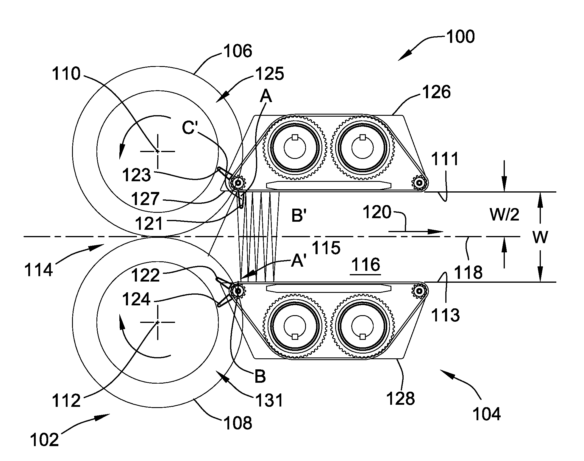
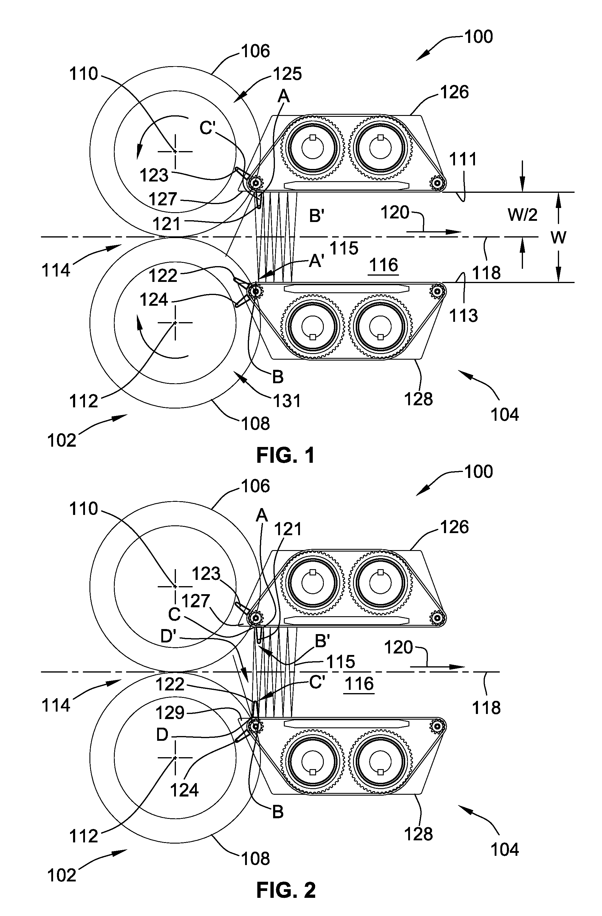
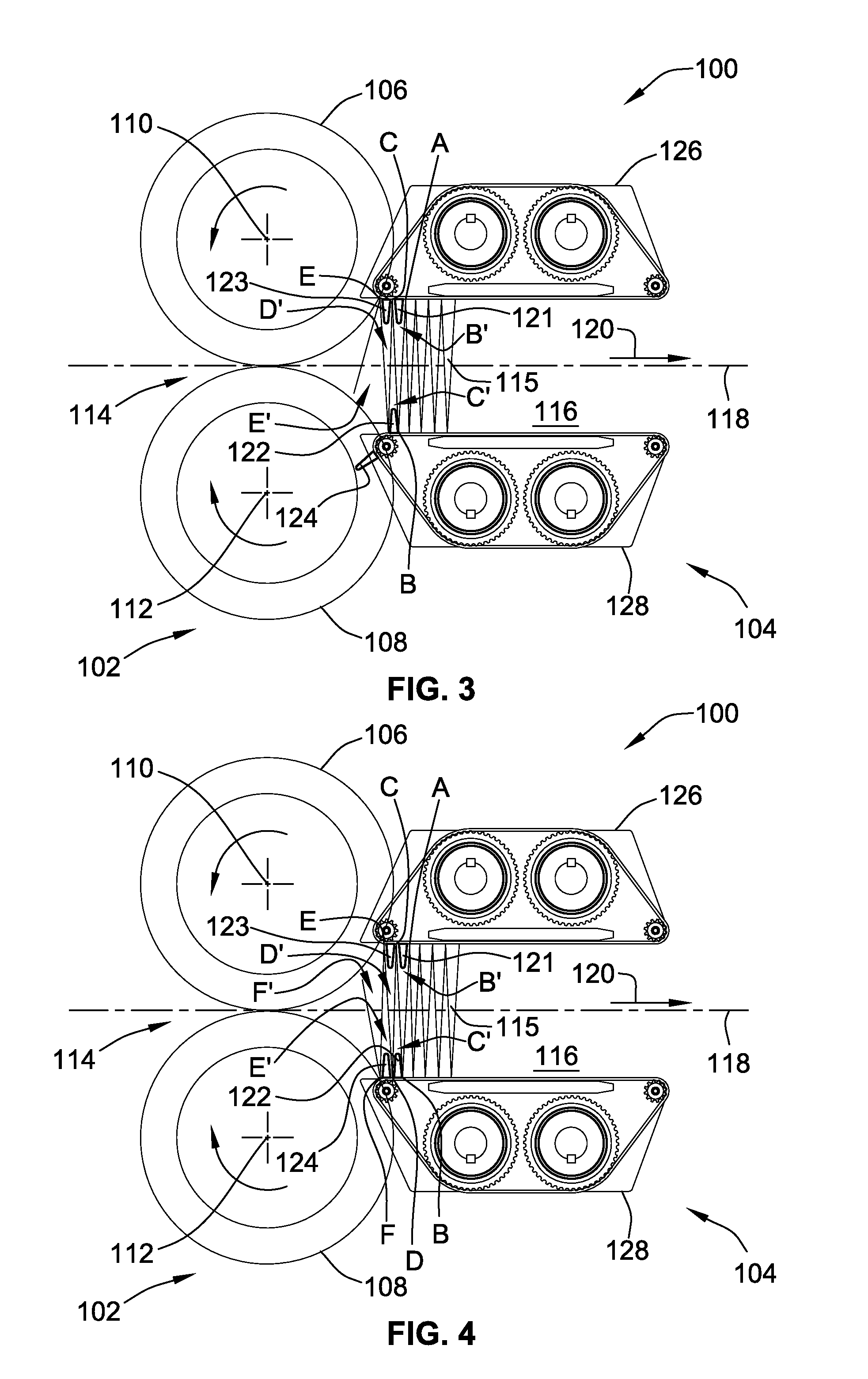
[0076]FIGS. 1-6 are schematic illustrations showing the construction and operation of an exemplary embodiment of a folding and separating apparatus 100 according to the invention. The folding and separating apparatus includes a folding arrangement 102 and a separating arrangement 104.

[0077]The folding arrangement 102 of the exemplary embodiment 100 is a typical counter-rotating folding roll arrangement of a type well known in the art. Specifically, the folding arrangement 102 includes a first and a second folding rolls 106, 108, mounted for counter-rotation about first and second folding roll axes 110, 112. The first and second roll axes 110, 112 extend parallel to one another, and the first and second rolls 106, 108 are positioned to form a nip 114 between outer peripheries 105, 107 of the rolls 106, 108.

[0078]A stream of cut sheets, or a web of material is fed through the nip 114 and folded or interfolded by the rolls 106, 108, into a desired folded configuration, such as one of t...


PUM

PropertyMeasurementUnit
Angleaaaaaaaaaa
Diameteraaaaaaaaaa
Speedaaaaaaaaaa

Abstract

The invention provides a method and apparatus for separating a stack of folded sheets by inserting a first, second, third and fourth count fingers into four successive openings in the stack, and separating the stack between the second and third count fingers. Where separation is carried out after a desired number of folded sheets have passed the third count finger, a completed pack having the desired number of sheets may be formed downstream from the third count finger. The count fingers may be operatively mounted in count finger cassettes.

Description

CROSS-REFERENCE TO RELATED PATENT APPLICATIONS[0001]This patent application is a Continuation-in-Part of co-pending U.S. patent application Ser. No. 12 / 759,784, filed Apr. 14, 2010, the entire teachings and disclosure of which are incorporated herein by reference thereto.FIELD OF THE INVENTION[0002]This invention relates to a method and apparatus for separating a stack of folded articles, such as paper towels, napkins, facial tissues or the like, into packs having a desired number of folded articles.BACKGROUND OF THE INVENTION[0003]There are many products, as exemplified by paper tissue, toweling and napkins, etc., which are commonly provided to consumers in stacked form as packs of folded or interfolded individual sheets. These packs of stacked sheets are often staple items which must be produced at very low cost. Producing such products at low cost typically requires the use of high-speed processes and equipment. Such processes are not limited to the production and delivery of pap...

Claims


Application Information

Patent Timeline
IPC IPC(8): B65H45/04B65H39/02B65H39/00B65H1/00B65H29/00B65H5/06B65H9/00
CPCB65H31/3045B65H31/32B65H33/02B65H45/04B65H2701/1924B65H2301/4214B65H2404/2321B65H2406/122B65H2701/18271B65H45/24
Inventor WALSH, JAMES ANDREW
Owner C G BRETTING MFG
Learn More