
Vehicle oil pump

a technology for oil pumps and vehicles, applied in the direction of machines/engines, liquid fuel engines, gearing, etc., can solve the problems of inability to supply the necessary oil when the oil pump is turned on, the structure is complicated, and the amount of oil may not be supplied when the vehicle travels backward

Inactive Publication Date: 2011-10-20
TOYOTA JIDOSHA KK +1
View PDF3 Cites 19 Cited by
  • Summary
  • Abstract
  • Description
  • Claims
  • Application Information

AI Technical Summary

Benefits of technology

[0008]In view of this, the invention provides a vehicle oil pump that is driven by a rotating shaft that rotates in one direction when a vehicle travels forward and rotates in the opposite direction when the vehicle travels backward, and that has a simple structure and is able to supply oil regardless of whether the vehicle is traveling forward or backward.
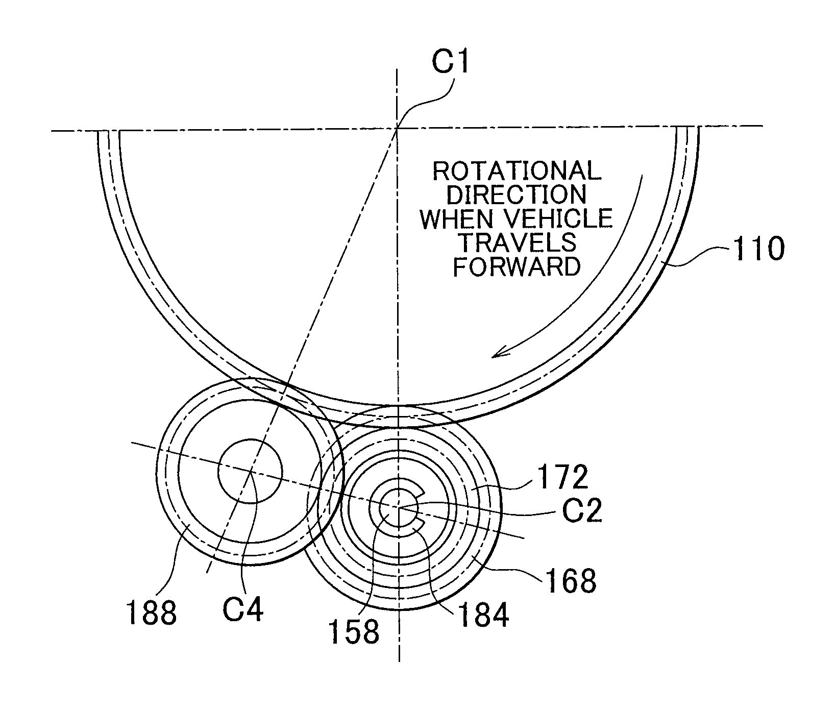
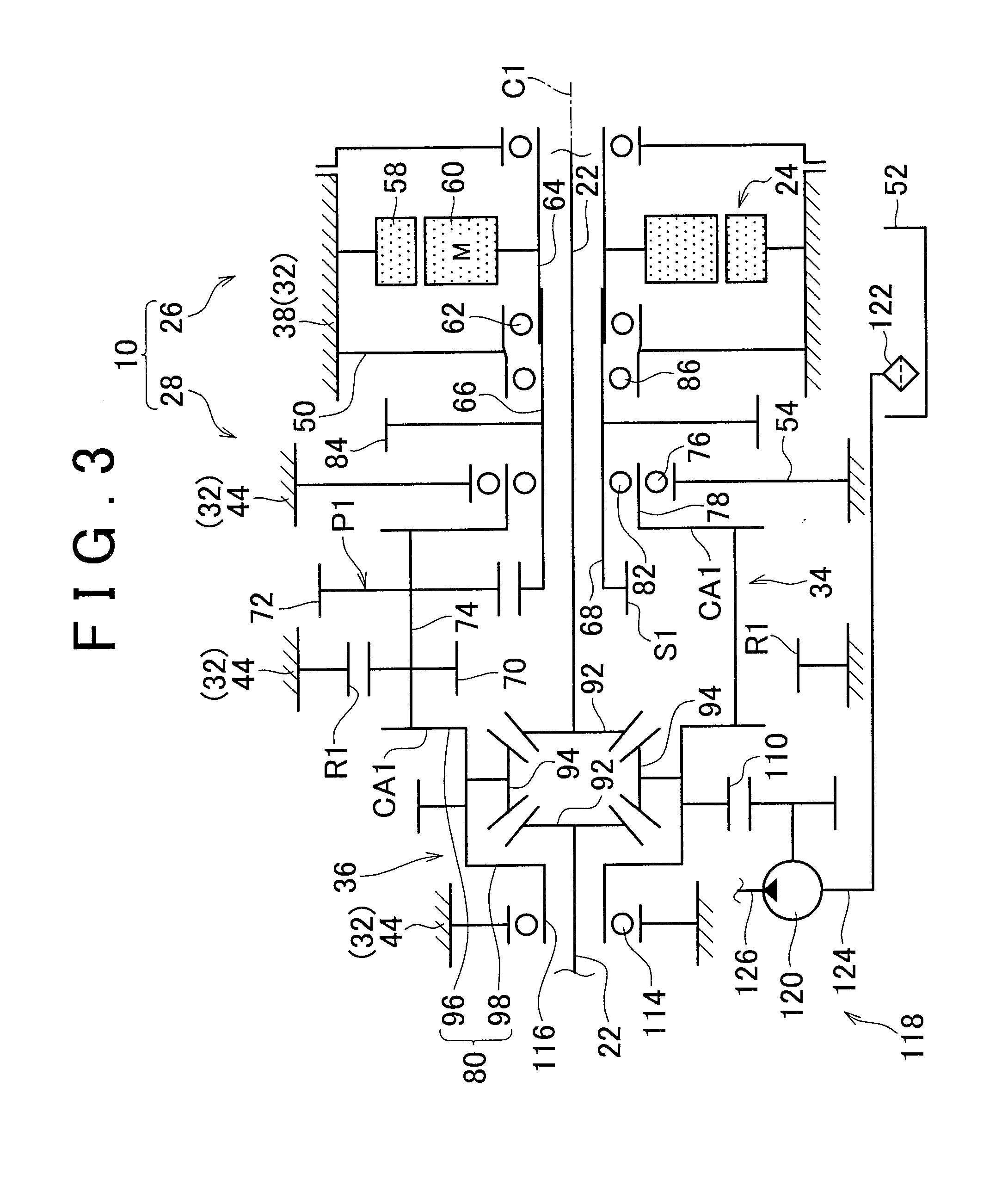
[0010]According to the vehicle oil pump described above, when the vehicle travels in one direction, i.e., either forward or backward, for example, the vehicle oil pump is driven by the first driven gear rotating the drive shaft of the vehicle oil pump via the first one-way clutch. At this time, the second driven gear rotates in the opposite direction of the first driven gear, but this rotation is not transmitted to the drive shaft because the second one-way clutch rotates idly. Also, when the vehicle travels in the other direction, i.e., either forward or backward, for example, the vehicle oil pump is driven by the second driven gear rotating the drive shaft of the vehicle oil pump via the second one-way clutch. At this time, the first driven gear rotates in the opposite direction of the second driven gear, but this rotation is not transmitted to the drive shaft because the first one-way clutch rotates idly. Here, the second driven gear is in mesh with the drive gear via the idler gear, so the rotational direction of the first driven gear when the vehicle travels forward is the same as the rotational direction of the second driven gear when the vehicle travels backward. As a result, the drive shaft of the oil pump rotates in the same direction when the vehicle travels backward as it does when the vehicle travels forward. Therefore, the vehicle oil pump is able to pump oil in the same direction regardless of whether the vehicle is traveling forward or backward, so oil can be supplied to portions of the vehicle requiring hydraulic pressure regardless of the direction in which the vehicle is traveling. Also, there is no need for a special switching mechanism or the like that switches the oil passage according to the direction in which the vehicle is traveling and the like, so the apparatus can be simplified, and in turn, the manufacturing cost can be reduced.
[0012]According to the vehicle oil pump described above, the radius of the pitch circle of the second driven gear is designed to be smaller than the radius of the pitch circle of the first driven gear, so even if the rotation speed of the drive gear is the same, the rotation speed of the drive shaft is relatively faster, and thus the discharge flowrate from the oil pump is relatively higher, when the vehicle is traveling backward than it is when the vehicle is traveling forward. As a result, oil is able to be effectively supplied when the vehicle is traveling backward at a comparatively low vehicle speed in which lubricating oil is especially necessary.
[0016]According to the vehicle oil pump described above, the face width of the drive gear is larger than the sum of the face width of the first driven gear and the face width of the idler gear, so the first driven gear and the idler gear are able to reliably be in mesh with the drive gear. As a result, torque is able to be reliably transmitted among gears, and the number of parts is able to be inhibited from increasing when making the invention.

Problems solved by technology

Therefore, when an oil pump is driven by a rotating shaft of the electric motor, the oil pump will end up rotating in the opposite direction when the vehicle travels backward, for example, and as a result, a sufficient amount of oil may not be able to be supplied when the vehicle travels backward.
That is, with a structure in which an oil pump is driven by a rotating shaft that rotates in one direction when the vehicle travels forward and rotates in the opposite direction when the vehicle travels backward, such as an output shaft of a vehicular power transmitting apparatus, the necessary oil is unable to be supplied when the oil pump rotates in the opposite direction while the vehicle is traveling backward, for example.
However, with the structure of the four-wheel-drive vehicle described in JP-A-10-217787, the need to provide the switching valve and the like complicates the structure and increases the number of parts, which in turn increases the manufacturing cost.

Method used


Image

  • Vehicle oil pump
  • Vehicle oil pump
  • Vehicle oil pump

Examples


Embodiment Construction

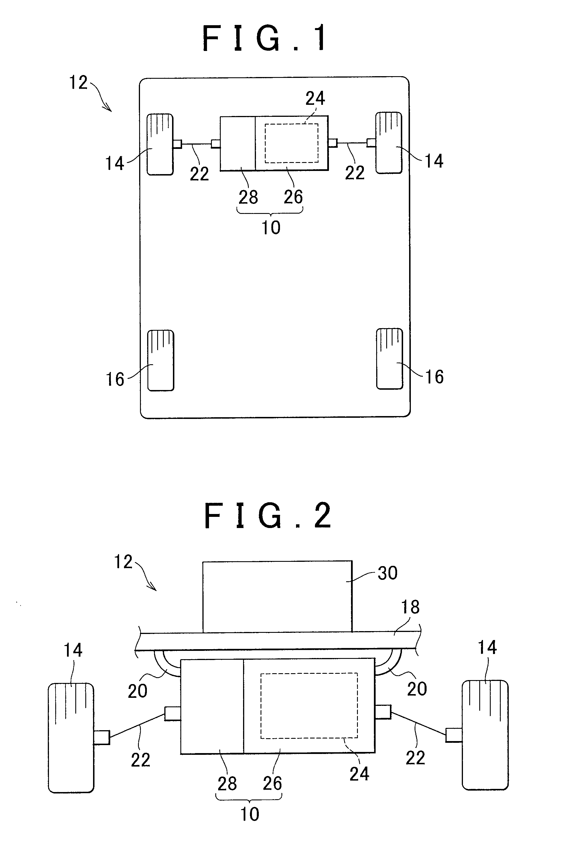
[0026]Here, the invention may be applied to an electric vehicle, for example. In the electric vehicle, the rotational direction of an electric motor that functions as a driving source changes according to the direction of travel of the vehicle. Therefore, the rotational direction of a drive gear that drives a vehicle oil pump also changes according to the direction of travel of the vehicle. Regarding this, applying the invention makes it possible to supply oil to portions that require oil in a vehicular power transmitting apparatus regardless of whether the direction of travel of the vehicle is forward or backward.

[0027]Also, an inner rotor of the vehicle oil pump is provided on a drive shaft that drives the vehicle oil pump. Therefore, when this drive shaft is rotated via a drive gear and a driven gear, the inner rotor is rotated and the oil pump is driven.

[0028]Hereinafter, example embodiments of the invention will be described in detail with reference to the accompanying drawings...


PUM


Abstract

A vehicle oil pump that is driven by a drive gear provided on a rotating shaft that rotates in one direction when a vehicle travels forward and rotates in the opposite direction when the vehicle travel backward includes a first driven gear that is in mesh with the drive gear and provided on a drive shaft of the vehicle oil pump via a first one-way clutch, an idler gear that is in mesh with the drive gear, and a second driven gear that is in mesh with the idler gear and provided on the drive shaft of the vehicle oil pump via a second one-way clutch. The first one-way clutch is configured to transmit rotation of the first driven gear to the drive shaft when the vehicle travels in one direction, from among forward and backward, and the second one-way clutch is configured to transmit rotation of the second driven gear to the drive shaft when the vehicle travels in the other direction, from among forward and backward.

Description

INCORPORATION BY REFERENCE[0001]The disclosure of Japanese Patent Application No. 2010-097440 filed on Apr. 20, 2010 including the specification, drawings and abstract is incorporated herein by reference in its entirety.BACKGROUND OF THE INVENTION[0002]1. Field of the Invention[0003]The invention relates to an oil pump provided in a vehicle. More particularly, the invention relates to a vehicle oil pump that has a structure in which a drive gear that drives the oil pump rotates in one direction when the vehicle travels forward and rotates in the opposite direction when the vehicle travels backward.[0004]2. Description of the Related Art[0005]In a power transmitting apparatus provided in a vehicle, hydraulic pressure of oil supplied to lubricating mechanisms and clutches that are driven by hydraulic pressure is generated by an oil pump that is a hydraulic pressure generating mechanism. A related oil pump is configured to be driven by a rotating shaft that rotates in a certain directi...

Claims


Application Information

Patent Timeline
Patent Type & Authority Applications(United States)
IPC IPC(8): F16H3/08
CPCF01C17/02F04C2/10F04C14/04Y10T74/19219F16H57/0441F16H57/0483F04C15/0061F16H3/003F16H37/082B60K2001/001
Inventor HARASHIMA, TERASUTESHIMA, ATSUSHISASAKI, YOSHIHIKOHAMAGUCHI, HIROSHI
Owner TOYOTA JIDOSHA KK
Learn More