Reinforced fan frame structure

a fan frame and reinforcement technology, applied in the direction of machines/engines, stators, liquid fuel engines, etc., can solve the problems of poor overall structural strength, the flatness of the seat portion b>12/b> just cannot be controlled to achieve the required specifications, and the conventional fan frame structure, etc., to achieve the effect of effective upgrading the overall structural strength of the seat portion, reducing the risk of damage, and reducing the damage to the frame body

Inactive Publication Date: 2011-10-06
ASIA VITAL COMPONENTS SHENZHEN CO LTD
View PDF9 Cites 1 Cited by
  • Summary
  • Abstract
  • Description
  • Claims
  • Application Information

AI Technical Summary

Benefits of technology

A primary object of the present invention is to provide a reinforced fan frame structure, which has at least one metal ring integrally associated with a seat portion of a frame body to thereby effectively upgrade the overall structural strength of the seat portion.
Another object of the present invention is to provide a reinforced fan frame structure, with which the deformation and flatness of a seat portion of a frame body can be effectively controlled.
A further object of the present invention is to provide a reinforced fan frame structure, which enables an increased adhesion effect between a rotor and a stator of the fan.
To achieve the above and other objects, the reinforced fan frame structure provided by the present invention includes a frame body and at least one metal ring. The frame body has a seat portion with a centered bearing cup axially forward extended from the seat portion. The metal ring is integrally associated with the seat portion and has an inner circumferential edge facing toward the bearing cup. With the metal ring integrally associated with the seat portion of the frame body, it is able to effectively control the deformation and the flatness of the seat portion and accordingly, effectively upgrade the overall structural strength of the seat portion.

Problems solved by technology

As can be seen in FIG. 1B, one problem with the conventional injection-molded frame body 1 is that the seat portion 12 therein would have depressions A or uneven pits formed on a surface of the recess 121 due to release of internal stress and the contraction property of the plastic material.
This condition will result in poor overall structural strength and accordingly, deformation of the seat portion 12.
Fan manufacturers tried to solve the above problems by modifying the mold and controlling different conditions for injection molding but failed.
Particularly, the flatness of the seat portion 12 just could not be controlled to achieve the required specifications and forms a difficult problem in the fan industry up to date.
In brief, the conventional fan frame structure has the following disadvantages: (1) having poor structural strength; (2) unable to control the deformation and flatness of the seat portion; and (3) being easy to deform.

Method used


Image

  • Reinforced fan frame structure
  • Reinforced fan frame structure
  • Reinforced fan frame structure

Examples


Embodiment Construction

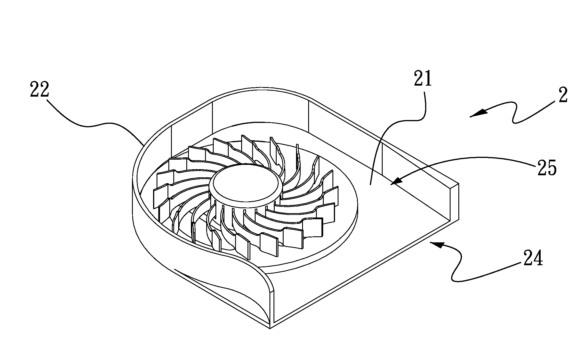
Please refer to FIGS. 2, 3, and 4 at the same time. A reinforced fan frame structure according to a preferred embodiment of the present invention includes a frame body 2 and at least one metal ring 3. The frame body 2 has a seat portion 20, a bottom portion 21, and a wall portion 22. The wall portion 22 is extended along an outer periphery of the bottom portion 21 to vertically rise from substantially three sides of the bottom portion 21, such that a receiving space 25 is defined in the frame body 2 by the wall portion 22 and the bottom portion 21. The seat portion 20 is located in the receiving space 25, and is provided with a centered and axially protruded bearing cup 201. The seat portion 20 is enclosed in an annular wall 202, so that an open-topped recess 204 is defined on the seat portion 20 within the annular wall 202. The metal ring 3 is located in the recess 204 and is integrally associated with the seat portion 20. More specifically, the metal ring 3 is disposed in the rece...


PUM


Abstract

A reinforced fan frame structure includes a frame body and at least one metal ring. The frame body has a seat portion with a centered bearing cup axially forward extended from the seat portion. The metal ring is integrally associated with the seat portion and has an inner circumferential edge facing toward the bearing cup. With the metal ring integrally associated with the seat portion of the frame body, it is able to effectively control the deformation and the flatness of the seat portion and accordingly, effectively upgrade the overall structural strength of the seat portion.

Description

FIELD OF THE INVENTIONThe present invention relates to a reinforced fan frame structure, and more particularly to a reinforced fan frame structure that has at least one metal ring integrally associated with a seat portion of the frame structure, so that the seat portion can have effectively increased overall structural strength and the deformation and flatness of the seat portion can be well controlled.BACKGROUND OF THE INVENTIONFollowing the progress in electronic information technology, various kinds of electronic products, such as desktop computers and notebook computers, have become highly popular and widely used in different applications. Moreover, all electronic products are designed to have gradually reduced sizes, particularly in their thickness to show a low profile. Taking a notebook computer as an example, since the current available notebook computer has largely reduced overall thickness to have only very limited heat dissipation therein, heat produced by the electronic ...

Claims


Application Information

Patent Timeline
Patent Type & Authority Applications(United States)
IPC IPC(8): F04D29/40
CPCF04D29/4226F04D25/0613
Inventor LEE, TA-CHENGYANG, CHING-MINWANG, CHUNG-SHU
Owner ASIA VITAL COMPONENTS SHENZHEN CO LTD
Why Eureka
Try Eureka