Color cathode ray tube

Inactive Publication Date: 2005-04-07
MERIDIAN SOLAR & DISPLAY
View PDF7 Cites 4 Cited by
  • Summary
  • Abstract
  • Description
  • Claims
  • Application Information

AI Technical Summary

Benefits of technology

[0017] Therefore, an object of the present invention is to provide a color CRT in which a reinforcing band position is optimized in order to effectively compensate a structural strength that is inevitably weakened as a CRT is increasingly light and slim.

Problems solved by technology

In this case, the peripheral portion and an edge portion of the CRT receive more vacuum stress than other portions, and thus are very weak in terms of structure.
In this respect, however, the lighter and slimmer the color CRT is, the weaker its structural strength is.
However, the conventional color CRT fails to optimize a width of the reinforcing band and a reinforcing band position, so there is a limitation to make the color CRT lighter and slimmer.

Method used


Image

  • Color cathode ray tube
  • Color cathode ray tube
  • Color cathode ray tube

Examples


Embodiment Construction

[0044] Reference will now be made in detail to the preferred embodiments of the present invention, examples of which are illustrated in the accompanying drawings.

[0045] For a better understanding of the present invention, some marks are given to position, shape and a tube axis directional distance of a color CRT based on which the color CRT of the present invention will now be described.

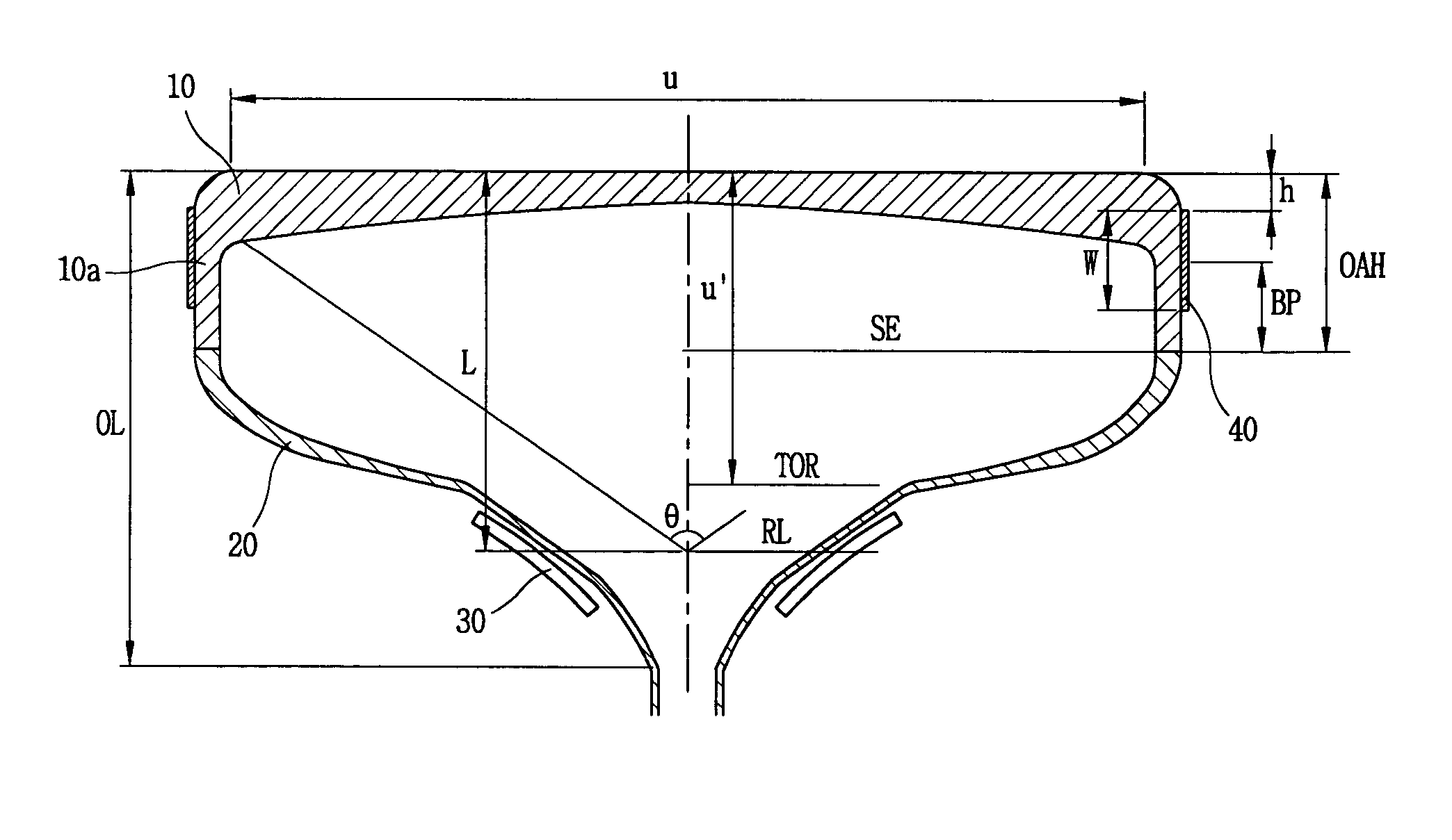
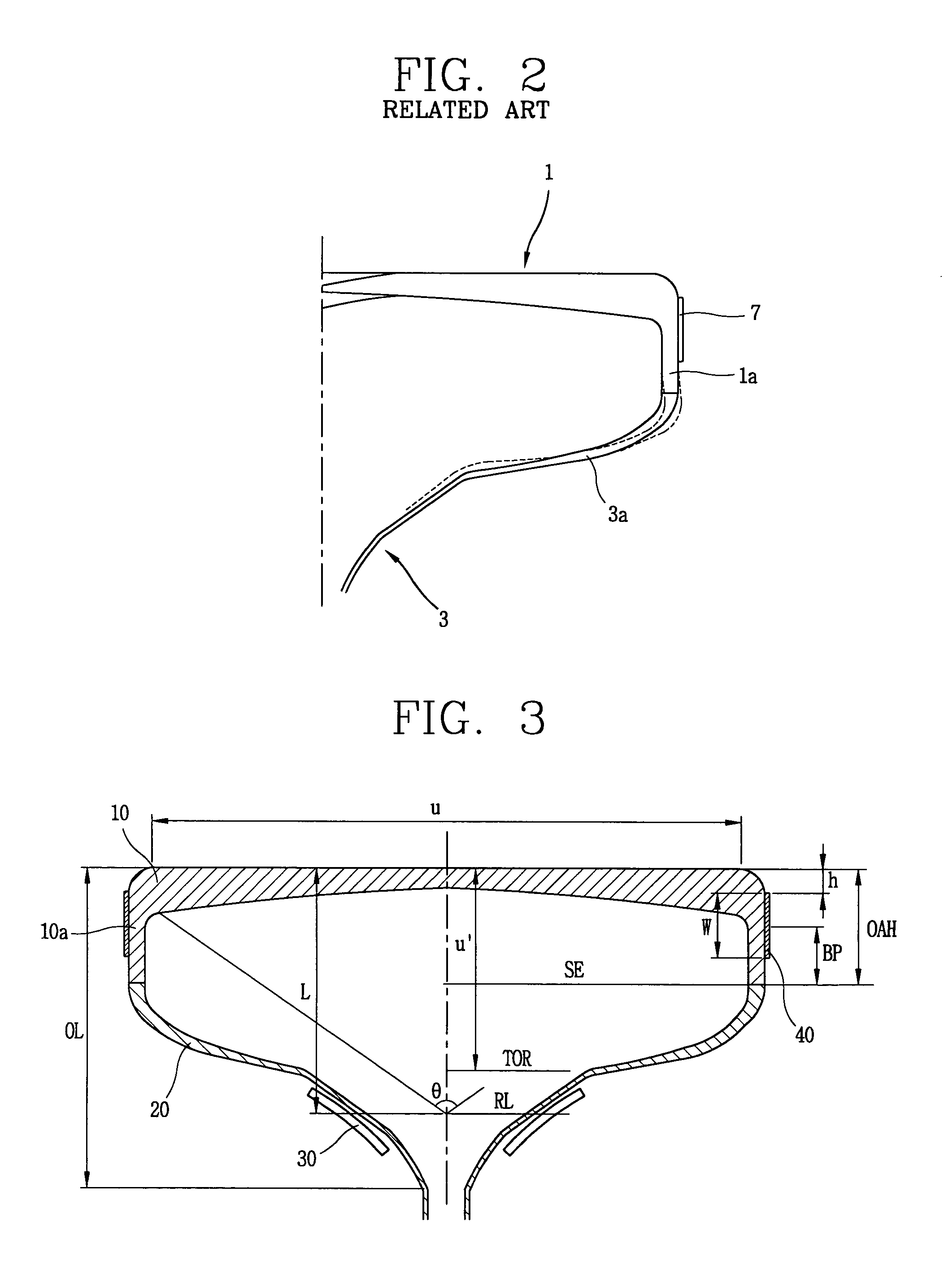
[0046]FIG. 3 is a vertical section view showing a structure of a color CRT in accordance with a present invention.

[0047] With reference to FIG. 3, a diagonal size of an effective surface is U; a tube axis directional distance from an outer surface center of a panel to a boundary portion between a body part and a yoke part of a funnel is U′; a tube axis directional distance from the outer surface center of the panel to a defection reference line of the funnel is L; a tube axis directional distance from the outer surface center of the panel to an end portion of the funnel is OL; a tube axis directio...


PUM


Abstract

A color cathode ray tube is disclosed. A color cathode ray tube including: a panel having a substantially flat outer surface and an inner surface having a curvature; a funnel coupled to the panel; a deflection yoke installed at an outer surface of the funnel; and a reinforcing band installed at a skirt portion of the panel, wherein the panel and the funnel satisfy the following condition, U / U′≧2.5, when a diagonal size of an effective surface of the panel is U, and a tube axis directional distance from an outer surface center of the panel to a boundary portion (TOR) between a body part and a yoke part of the funnel is U′, so that In the color cathode ray tube of the present invention, a lightness and slimness of a panel can be accomplished, and in order to compensate the weak structural strength caused in this case, a reinforcing band position (h) is set in the range of 10.5 mm˜20 mm to implement an optimum tensile force.

Description

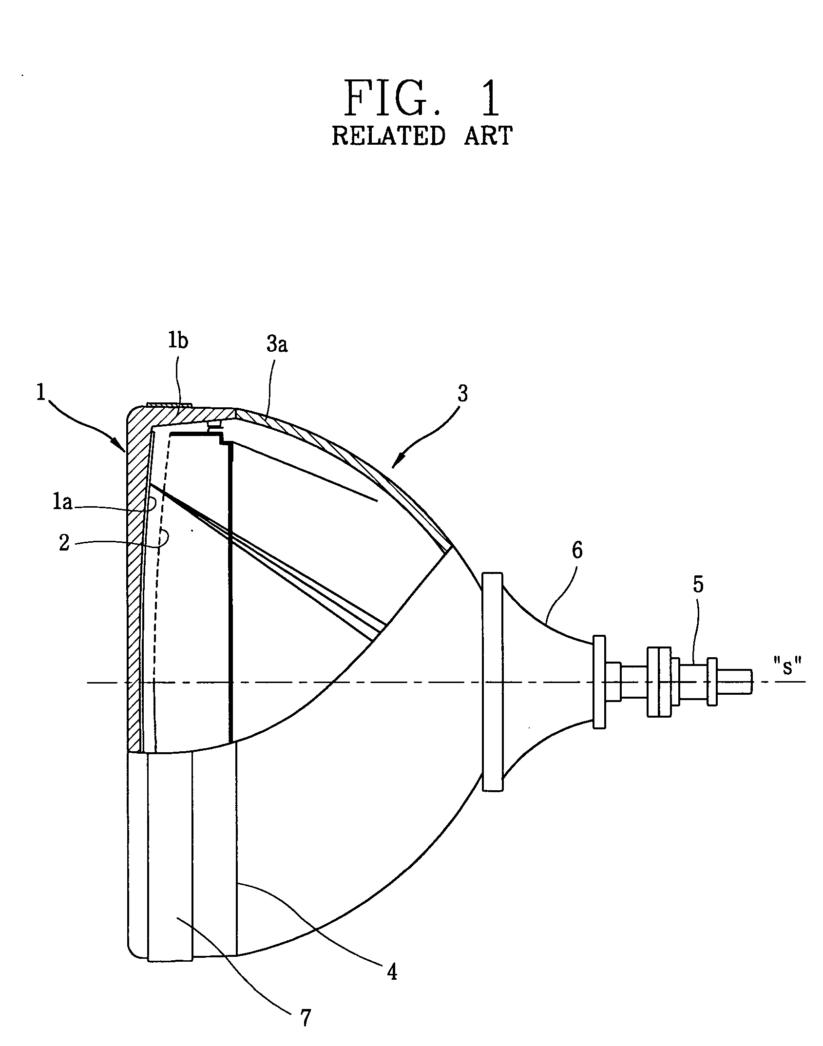
BACKGROUND OF THE INVENTION [0001] 1. Field of the Invention [0002] The present invention relates to a color cathode ray tube (CRT) and, more particularly, to a color cathode ray tube in which structure of the cathode ray tube is optimally made light and slim. [0003] 2. Description of the Related Art [0004] In general, a cathode ray tube is a sort of the widely used display device, which implements an image as electron beams from an electron gun therein hit a phosphor screen in a high pressure vacuum state. [0005]FIG. 1 is a partially sectioned side view showing an interior of a general color CRT [0006] As shown in FIG. 1, a general color cathode ray tube includes: a panel 1 formed with a substantially flat outer surface and an inner surface with a certain curvature; a shadow mask 2 disposed with at a certain interval from the inner side of the panel 1; a funnel coupled to the panel 1; a seal edge line 4 formed at a connecting portion between the funnel 3 and the panel 1; an electro...

Claims


Application Information

Patent Timeline
IPC IPC(8): H01J29/86H01J29/87
CPCH01J29/861H01J2229/862H01J29/87
Inventor BAEK, JAE-SEUNGPARK, JIN-MOK
Owner MERIDIAN SOLAR & DISPLAY
Why Eureka
Try Eureka