
Semiconductor Device and Method of Forming RF Balun Having Reduced Capacitive Coupling and High CMRR

Active Publication Date: 2011-10-06
JCET SEMICON (SHAOXING) CO LTD
View PDF2 Cites 21 Cited by
  • Summary
  • Abstract
  • Description
  • Claims
  • Application Information

AI Technical Summary

Benefits of technology

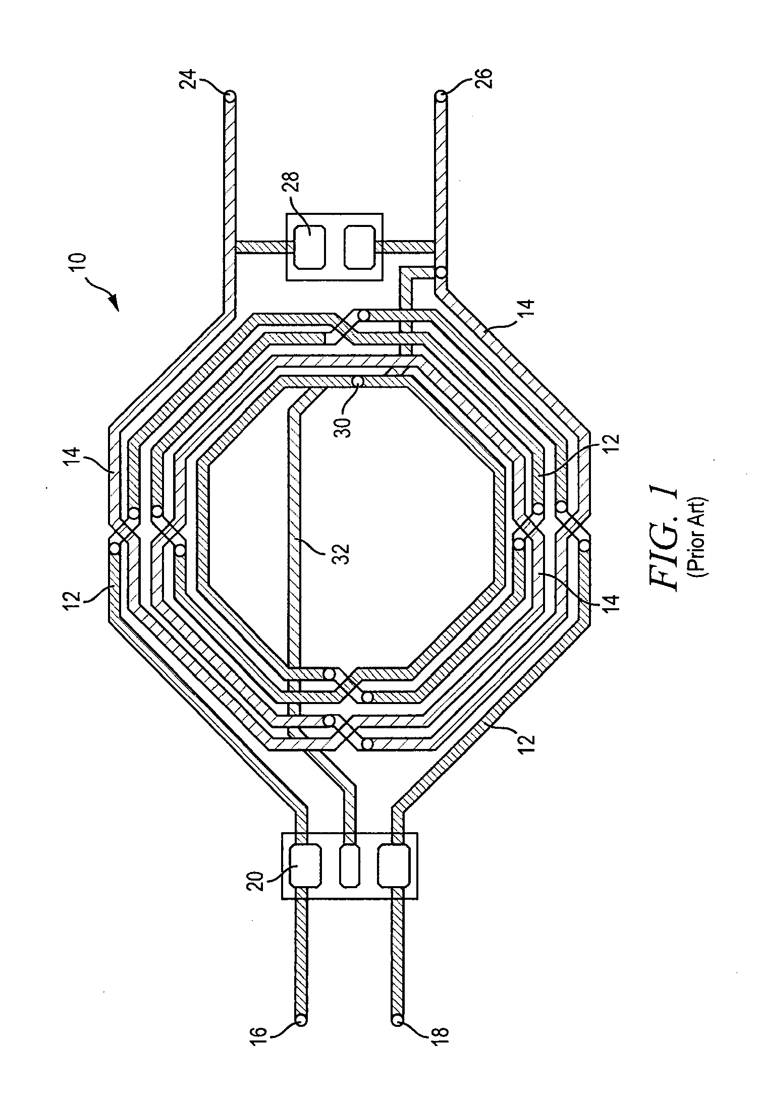
[0014]A need exists for an RF balun with reduced capacitive coupling and high CMRR. Accordingly, in one embodiment, the present invention is a semiconductor device comprising a substrate and balun formed over the substrate. The balun includes a first conductive trace wound to exhibit inductive properties with a first end coupled to a first terminal of the semiconductor device and second end coupled to a second terminal of the semiconductor device. A first capacitor is coupled

Problems solved by technology

An insufficient CMRR results in power supply modulation and self-mixing in receiver circuits, such as the low noise amplifier.
However, parasitic capacitive coupling between LC resonators allows leakage of the common-mode signal to the unbalanced port, particularly at higher frequencies.
While the larger balun with interleaved conduc

Method used


Image

  • Semiconductor Device and Method of Forming RF Balun Having Reduced Capacitive Coupling and High CMRR
  • Semiconductor Device and Method of Forming RF Balun Having Reduced Capacitive Coupling and High CMRR
  • Semiconductor Device and Method of Forming RF Balun Having Reduced Capacitive Coupling and High CMRR

Examples


Example

DETAILED DESCRIPTION OF THE DRAWINGS

[0027]The present invention is described in one or more embodiments in the following description with reference to the figures, in which like numerals represent the same or similar elements. While the invention is described in terms of the best mode for achieving the invention's objectives, it will be appreciated by those skilled in the art that it is intended to cover alternatives, modifications, and equivalents as may be included within the spirit and scope of the invention as defined by the appended claims and their equivalents as supported by the following disclosure and drawings.

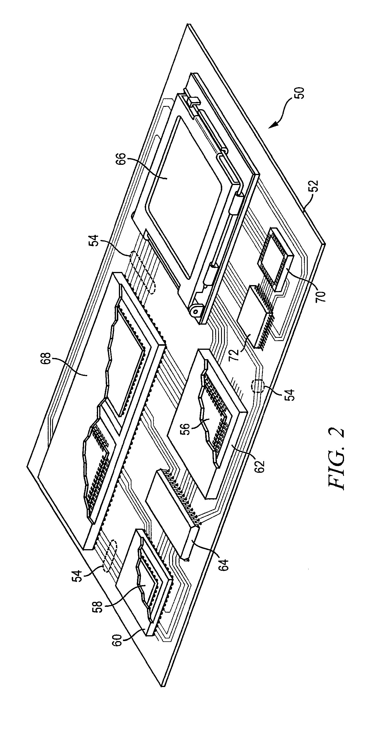
[0028]Semiconductor devices are generally manufactured using two complex manufacturing processes: front-end manufacturing and back-end manufacturing. Front-end manufacturing involves the formation of a plurality of die on the surface of a semiconductor wafer. Each die on the wafer contains active and passive electrical components, which are electrically connected to f...


PUM

PropertyMeasurementUnit
Lengthaaaaaaaaaa
Shapeaaaaaaaaaa
Electrical conductoraaaaaaaaaa

Abstract

A semiconductor device has an RF balun formed over a substrate. The RF balun includes a first conductive trace wound to exhibit inductive properties with a first end coupled to a first terminal of the semiconductor device and second end coupled to a second terminal of the semiconductor device. A first capacitor is coupled between the first and second ends of the first conductive trace. A second conductive trace is wound to exhibit inductive properties with a first end coupled to a third terminal of the semiconductor device and second end coupled to a fourth terminal of the semiconductor device. The first conductive trace is formed completely within the second conductive trace. The first conductive trace and second conductive trace can have an oval, circular, or polygonal shape separated by 50 micrometers. A second capacitor is coupled between the first and second ends of the second conductive trace.

Description

FIELD OF THE INVENTION[0001]The present invention relates in general to semiconductor devices and, more particularly, to a semiconductor device and method of forming an RF balun having reduced capacitive coupling between LC resonators and high CMRR.BACKGROUND OF THE INVENTION[0002]Semiconductor devices are commonly found in modern electronic products. Semiconductor devices vary in the number and density of electrical components. Discrete semiconductor devices generally contain one type of electrical component, e.g., light emitting diode (LED), small signal transistor, resistor, capacitor, inductor, and power metal oxide semiconductor field effect transistor (MOSFET). Integrated semiconductor devices typically contain hundreds to millions of electrical components. Examples of integrated semiconductor devices include microcontrollers, microprocessors, charged-coupled devices (CCDs), solar cells, and digital micro-mirror devices (DMDs).[0003]Semiconductor devices perform a wide range o...

Claims


Application Information

Patent Timeline
IPC IPC(8): H03H5/02H01L21/60
CPCH01L23/5223Y10T29/41H01L2924/09701H01L2924/3011H01L23/5227H01L2924/13091H01L2924/30107H01L2224/73265H01L2224/48247H01L2224/48091H01L2224/16225H01L2924/00014H01L2924/00H01L2924/181H01L2924/00012
Inventor FRYE, ROBERT C.LIU, KAI
Owner JCET SEMICON (SHAOXING) CO LTD
Learn More