Instruction fetch apparatus, processor and program counter addition control method
- Summary
- Abstract
- Description
- Claims
- Application Information
AI Technical Summary
Benefits of technology
Problems solved by technology
Method used
Image
Examples
first embodiment
1. First Embodiment
Structure of the Processor
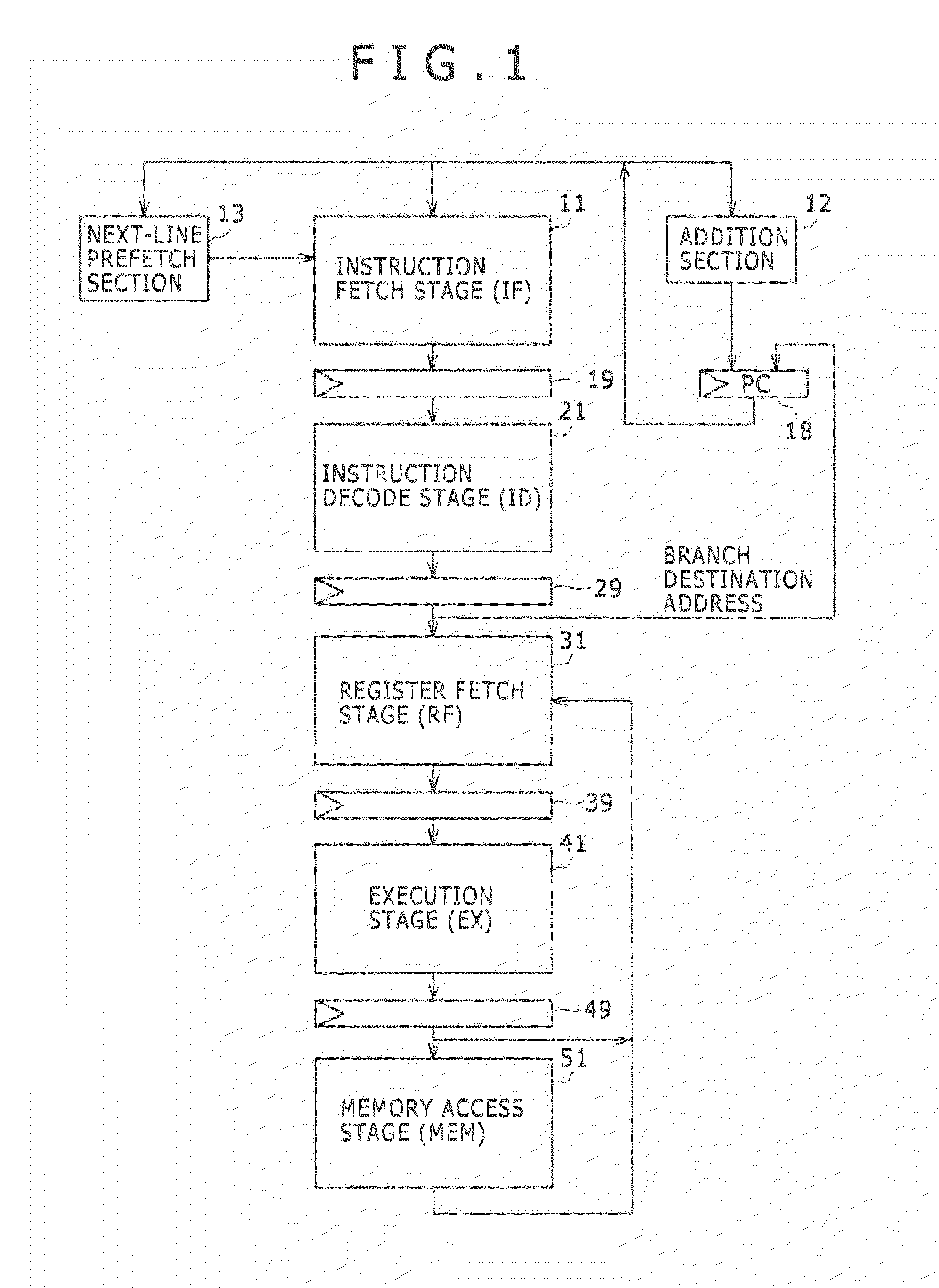
[0060]FIG. 1 is a schematic view showing a typical pipeline structure of a processor constituting part of the first embodiment of the present invention. This example presupposes five pipeline stages: an instruction fetch stage (IF) 11, an instruction decode stage (ID) 21, a register fetch stage (RF) 31, an execution stage (EX) 41, and a memory access stage (MEM) 51. The pipelines are delimited by latches 19, 29, 39, and 49. Pipeline processing is carried out in synchronization with a clock.
[0061]The instruction fetch stage (IF) 11 involves performing instruction fetch processing. At the instruction fetch stage 11, a program counter (PC) 18 is sequentially incremented by an addition section 12. The instruction pointed to by the program counter 18 is sent downstream to the instruction decode stage 21. Also, the instruction fetch stage 11 includes an instruction cache (to be discussed later) to which an instruction is prefetched. A next-line...
second embodiment
2. Second Embodiment
[0119]The above-described first embodiment presupposed that programs are managed using instruction packets. However, this type of management is not mandatory for the second embodiment of the present invention. Explained first below will be instruction prefetch control without recourse to instruction packets, followed by an explanation of instruction prefetch using instruction packets. The pipeline structure and block structure of the second embodiment are the same as those of the first embodiment and thus will not be discussed further.
[Branch Instruction Placement and Instruction Prefetch Start Locations]
[0120]FIG. 13 is a schematic view showing typical relations between the placement of a branch instruction and the start location of instruction prefetch in connection with the second embodiment of the present invention. The branch destination of a branch instruction $1 found in a cache line #1 is included in a cache line #3. Thus if the branch instruction $1 is e...
third embodiment
3. Third Embodiment
[0154]The first and the second embodiments described above were shown to address the control over whether or not to inhibit next-line prefetch. The third embodiment of the invention to be described below, as well as the fourth embodiment to be discussed later, will operate on the assumption that both the next line and the branch destination line are prefetched. The pipeline structure and block structure of the third embodiment are the same as those of the first embodiment and thus will not be explained further.
[Addition Control Process of the Program Counter]
[0155]FIG. 20 is a schematic view showing a typical functional structure of a program counter for addition control processing in connection with the third embodiment of the present invention. This functional structure example includes an instruction fetch section 610, an instruction decode section 620, an instruction execution section 630, an addition control register 640, an addition control section 650, and ...
PUM
 Abstract
Description
Claims
Application Information
 - R&D
- Intellectual Property
- Life Sciences
- Materials
- Tech Scout
- Unparalleled Data Quality
- Higher Quality Content
- 60% Fewer Hallucinations
Browse by: Latest US Patents, China's latest patents, Technical Efficacy Thesaurus, Application Domain, Technology Topic, Popular Technical Reports.
© 2025 PatSnap. All rights reserved.Legal|Privacy policy|Modern Slavery Act Transparency Statement|Sitemap|About US| Contact US: help@patsnap.com


