
Use of electric fields to minimize rejection of implanted devices and materials

a technology of implanted devices and materials, applied in the field of use of electric fields, can solve the problems that the passive control of the rejection response by itself has not always proved effective, and achieve the effect of minimizing the formation of fibrous capsules

Inactive Publication Date: 2011-09-15
PHILOMETRON
View PDF2 Cites 16 Cited by
  • Summary
  • Abstract
  • Description
  • Claims
  • Application Information

AI Technical Summary

Benefits of technology

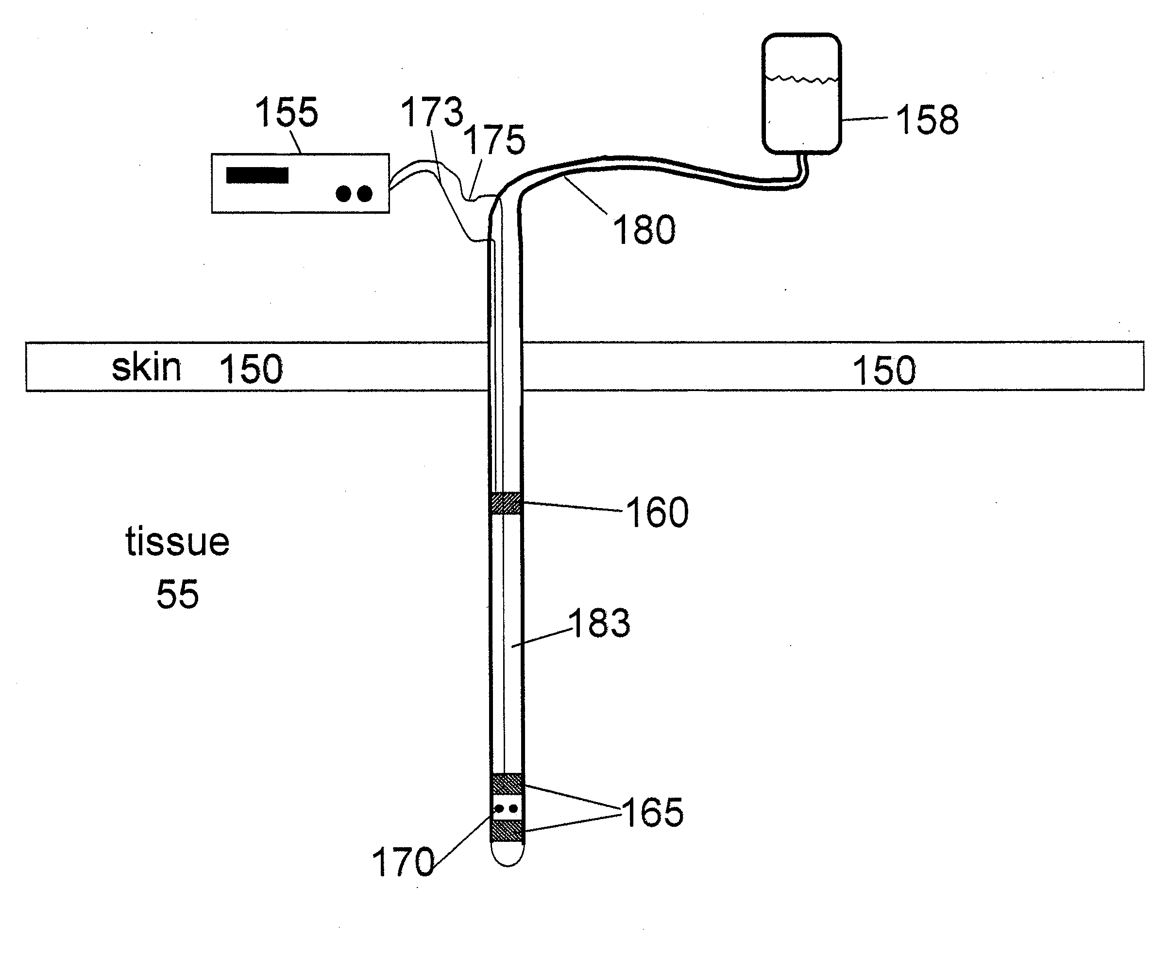
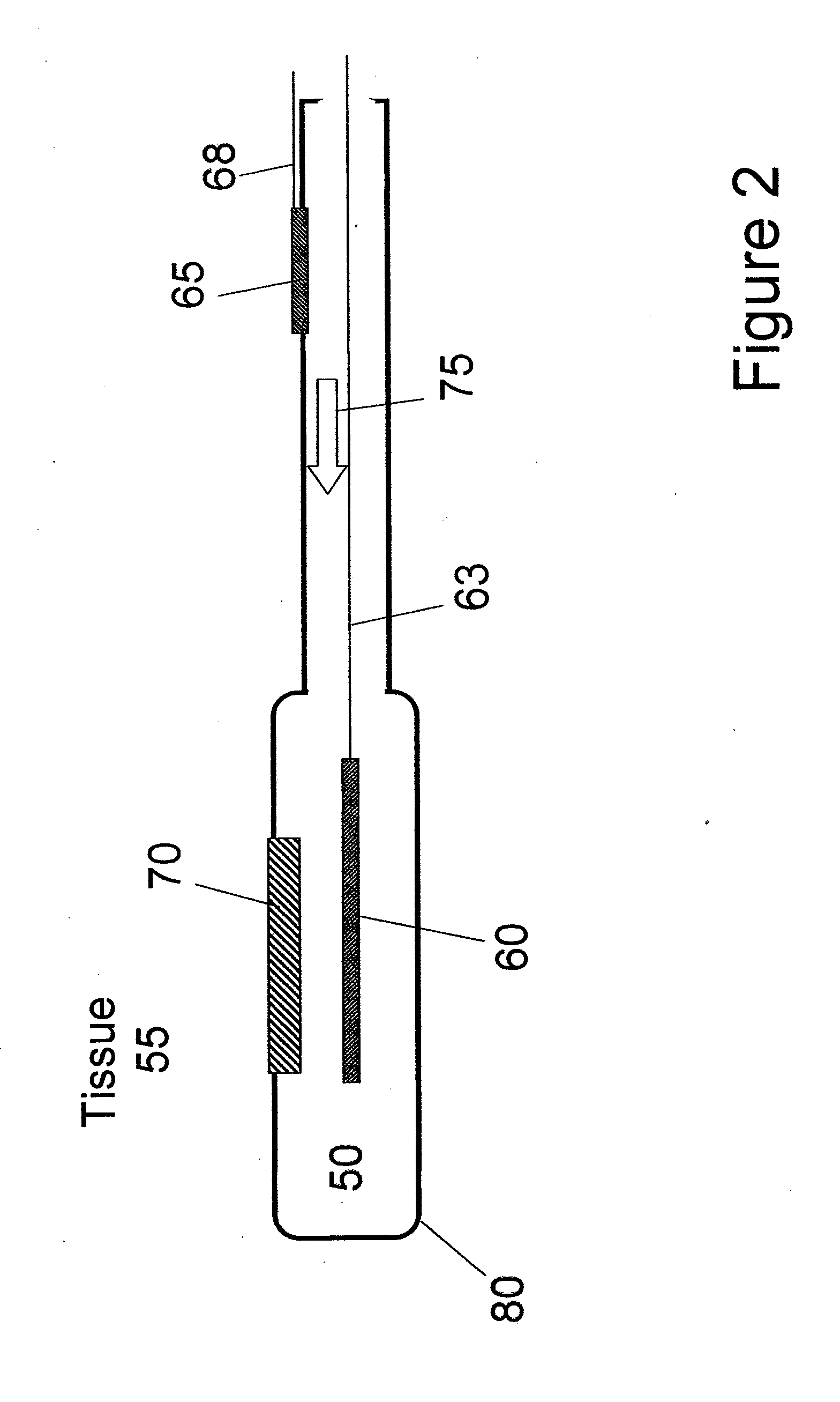
[0010]The method of this invention includes the application of electrical currents through subcutaneous tissue through at least one active first electrode positioned in close proximity to a critical feature of an implanted or subcutaneous medical device to at least one second electrode located elsewhere either on the device or otherwise enabling completion of the electrical circuit. It is the object of this invention that by use of these electrical currents, fibrous capsule formation in the vicinity of one or more critical features is reduced or eliminated thereby improving device performance and useful lifetime.
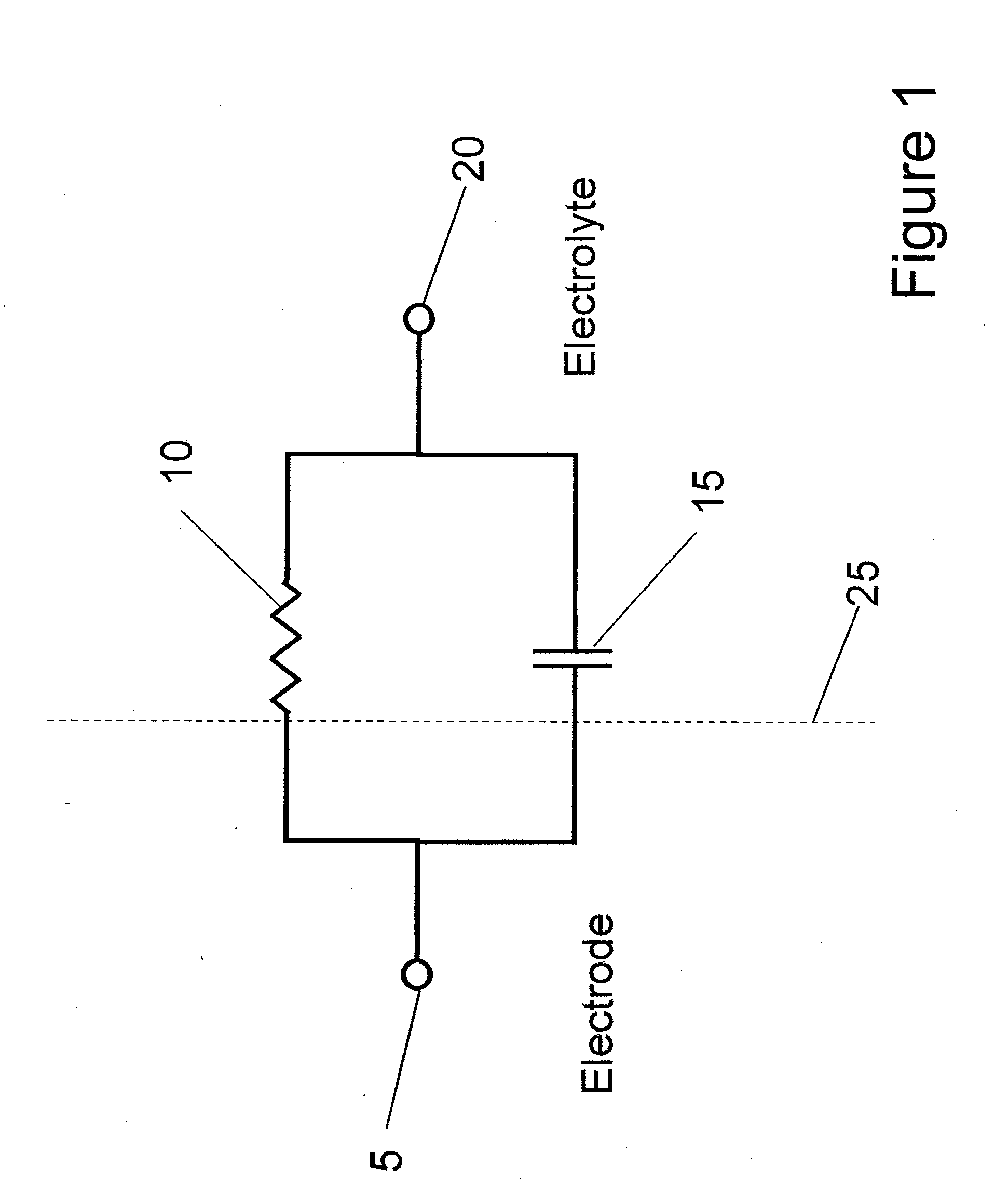
[0013]Embodiments of the method and apparatus of the invention also includes the use of structures, materials or electrical current protocols useful for diminishing possible deleterious effects resultant from the introduction of an electrical current into a fluid, e.g. electrolysis by-products. In one embodiment of the invention, the use of pulsatile currents is utilized to reduce possible deleterious effects. In yet other embodiments of the invention, the electrode surface is separated from contact with surrounding tissue using structures such as porous coatings, gels, sequestration within lumen of devices or by use of mesh-like screens. Such separation permits additional features, e.g. natural buffering capacity, to ameliorate possible deleterious effects resultant from the introduction of the electrical current.

Problems solved by technology

Such passive means to control the rejection response by themselves have not always proved effective.

Method used


Image

  • Use of electric fields to minimize rejection of implanted devices and materials
  • Use of electric fields to minimize rejection of implanted devices and materials
  • Use of electric fields to minimize rejection of implanted devices and materials

Examples


Embodiment Construction

e or more subdermal regions of a subject.[0029]5. Electrophoresis—The movement of molecules or particles (possessing a net charge) under the influence of an electric field. This electric field results from the passage of an electric current through solution containing charged particles from one electrode to another.[0030]6. Subdermal—Beneath the skin. In the context of this invention, this region may include, but is not limited to, tissues, organs, cavities, fluids, vascular or connective structures located within the body of a subject. In this context, subdermal also includes regions of the dermis that would be pierced or other penetrated by devices such as microdelivery needles.[0031]7. Subject—A human or mammalian subject who has one or more devices employing the apparatus of this invention.

DETAILED DESCRIPTION OF THE INVENTION

[0032]The invention generally relates to novel use of electric fields to diminish the body's rejection response to implanted drug delivery and biofluid sam...


PUM


Abstract

This invention relates to the electric field method to reduce fibrous capsule formation adjacent to the surface of implanted medical devices and associated apparatus for generating electrical currents to reduce fibrous capsule formation. The invention has utility with medical devices or systems such as those providing long term parenteral drug delivery, fluid infusion or analyte sampling / measurement. The apparatus of the invention may be constructed as a part of the medical device or may be constructed of separate elements while providing the benefit of the electric fields to the medical device.

Description

CROSS-REFERENCE TO RELATED APPLICATIONS[0001]This application is a continuation of U.S. application Ser. No. 10 / 722,306 filed on Nov. 24, 2003, which application claims the benefit of U.S. Provisional Application 60 / 428,583, filed on Nov. 22, 2002.FIELD OF THE INVENTION[0002]This invention relates to the use of electric fields to reduce fibrous capsule formation adjacent to the surface of implanted medical devices. Reduced capsule formation facilitates the transfer of fluids into or out of an interior lumen of an implanted device and the surrounding tissue or between the surface of an implanted device and surrounding tissue. Medical devices employing such electric fields may be part of a drug delivery system / device or a biofluid sampling system / device intended for use within a mammalian body. The invention provides for methods and apparatus to supply electric currents to generate such fields as either stand alone apparatus or as part of larger medical devices or systems.BACKGROUND O...

Claims


Application Information

Patent Timeline
IPC IPC(8): A61N1/00A61N1/20A61N1/32A61M5/00A61B5/00A61N1/05
CPCA61N1/05A61N1/326A61N1/32
Inventor EDMAN, CARL FREDERICKDRINAN, DARREL DEAN
Owner PHILOMETRON
Learn More