
Electrostatic Discharge Protection Rail Clamp with Discharge Interruption Circuitry

a technology of protection circuitry and discharge interruption, applied in the direction of emergency protection circuit arrangement, emergency protection arrangement for limiting excess voltage/current, electric devices, etc., can solve the problem of exceeding the breakdown threshold of the component, increasing the risk of esd events, and damage from excessive voltage or damag

Active Publication Date: 2011-09-15
SILICON LAB INC
View PDF5 Cites 26 Cited by
  • Summary
  • Abstract
  • Description
  • Claims
  • Application Information

AI Technical Summary

Benefits of technology

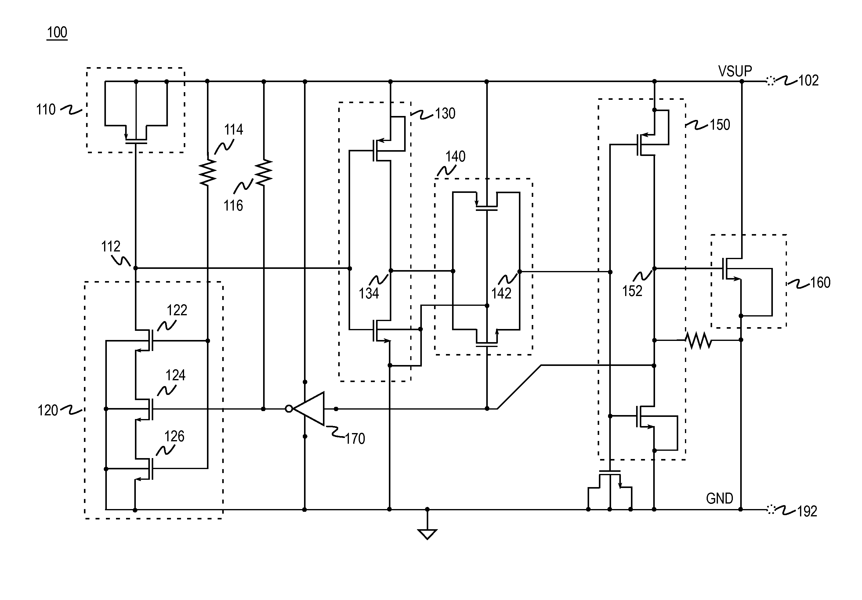
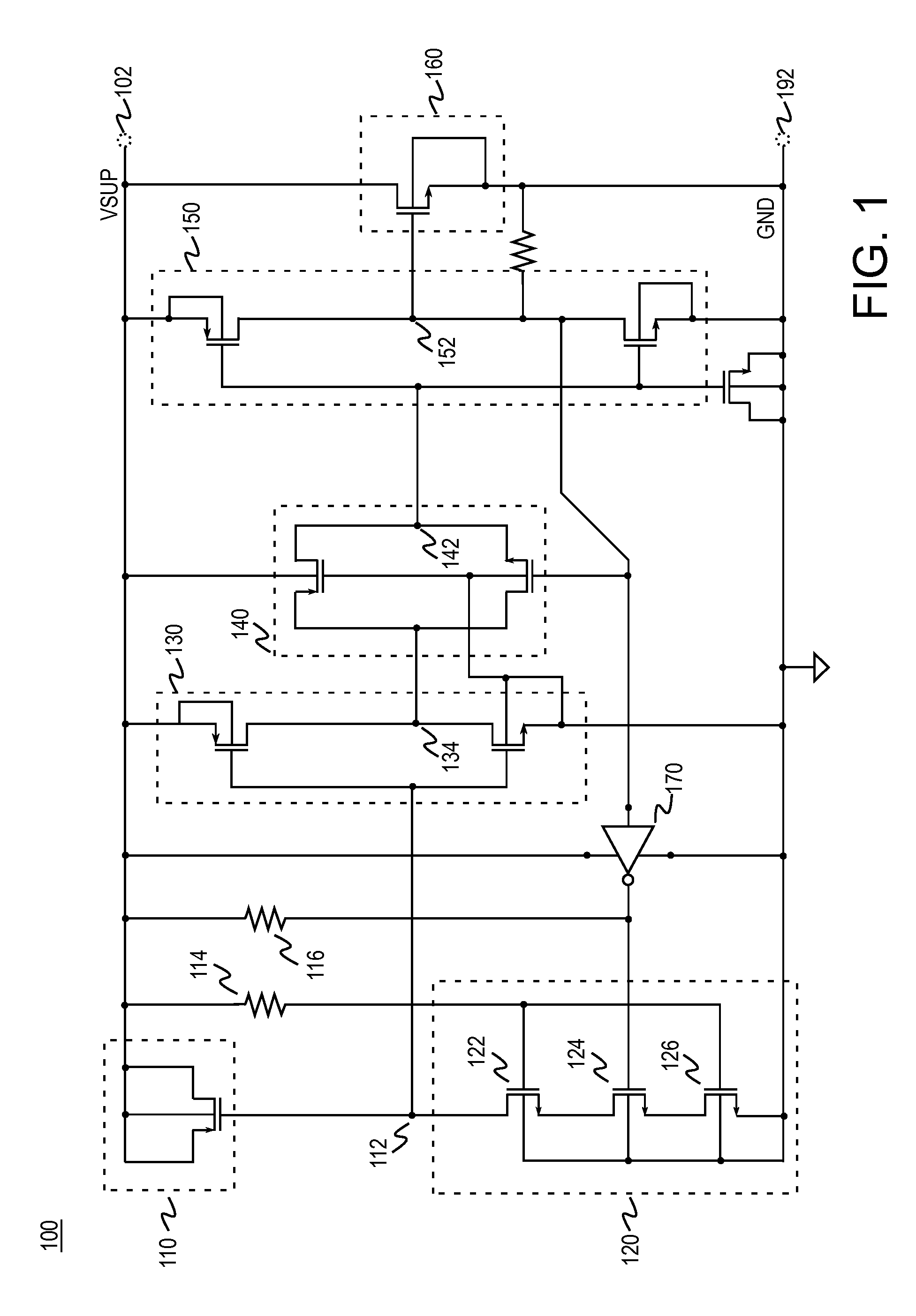
The patent describes methods and devices used to protect electronic circuits from damage caused by electrostatic discharge (ESD). One method involves using a shunt to short-circuit two nodes in the circuit in response to an ESD event. The activation circuitry that enables the shunt is designed to detect the ESD event and provide a time constant for the process. The patent also describes an apparatus that includes the activation circuitry and a selectable load, which affects the time constant. The technical effect of this patent is to provide a reliable and effective way to protect electronic circuits from ESD damage.

Problems solved by technology

The voltage potential from accumulated charge may exceed the component's breakdown threshold and lead to damage from excessive voltage or damage from the resulting discharge currents.
As electrical devices and components have become smaller, they have become more susceptible to harm from ESD events.
Component damage can occur due to a discharge or from the accumulation of charge.
The smaller time constant can cause the ESD protection circuitry to inadequately dissipate the charge or to take an undesirably long time to dissipate the charge.
One disadvantage of the long time constant, however, is that the ESD protection circuit may be less capable of consistently and reliably distinguishing an ESD event from other transient events such as a power-up.
Another disadvantage of typical long time constant shunt designs is the relatively large semiconductor die area used to implement the long time constant.

Method used


Image

  • Electrostatic Discharge Protection Rail Clamp with Discharge Interruption Circuitry
  • Electrostatic Discharge Protection Rail Clamp with Discharge Interruption Circuitry
  • Electrostatic Discharge Protection Rail Clamp with Discharge Interruption Circuitry

Examples


Embodiment Construction

[0017]An imbalance of electrical charge on the surface of an object is referred to as an electrostatic charge or static electricity. An electrostatic charge can accumulate onto an object by various means including contact with another charged object, induction, and ion bombardment.

[0018]Electrostatic charge can also be accumulated through triboelectric charging. Triboelectric charging occurs due to the transference of electrons from the surface of one object to the other object. Triboelectric charging can occur as a result of contact and subsequent separation of two objects even if the objects are electrically neutral or at the same electrical potential (i.e., relative neutrality).

[0019]The accumulation of electrostatic charge from typical manufacturing tasks may result in a change in electrical potential by several thousands or even tens of thousands of volts. The amount of charge can be altered by subsequent electrostatic discharge (ESD). ESD is a transfer of charge between object...


PUM


Abstract

An electrostatic discharge (ESD) protection circuit apparatus is disclosed. The apparatus includes activation circuitry coupled to a first node. The activation circuitry includes a capacitor and a selectable load. A time constant τ associated with the activation circuitry varies in accordance with the selectable load. The activation circuitry is configured to provide τ=τ1 for detection of an ESD event. A shunt is selectively enabled by the activation circuitry to short the first node to a second node in accordance with the detection of the ESD event. The activation circuitry is configured subsequent detection of the ESD event to provide τ=τ2, wherein τ2>τ1.

Description

TECHNICAL FIELD[0001]The invention is directed toward electrostatic discharge protection circuitry.BACKGROUND OF THE INVENTION[0002]The amount of electrostatic charge on an object can be rapidly altered as a result of an electrostatic discharge (ESD) event. An ESD event can alter the electrical characteristics of circuitry including semiconductor components so as to degrade or destroy the components. The voltage potential from accumulated charge may exceed the component's breakdown threshold and lead to damage from excessive voltage or damage from the resulting discharge currents. As electrical devices and components have become smaller, they have become more susceptible to harm from ESD events.[0003]ESD events impact production yields, product quality, and product reliability. ESD events can occur throughout manufacturing, testing, shipping, handling, or use of a product. Component damage can occur due to a discharge or from the accumulation of charge. Ample opportunities for an ES...

Claims


Application Information

Patent Timeline
Patent Type & Authority Applications(United States)
IPC IPC(8): H02H9/04
CPCH02H9/046
Inventor SMITH, JEREMY C.
Owner SILICON LAB INC
Learn More