Inductively coupled ac power transfer

a technology of inductive coupling and power transfer, applied in the direction of electric vehicle charging technology, inductance, transportation and packaging, etc., can solve the problem of clear less efficiency than, and achieve the effect of small loss

Active Publication Date: 2011-09-15
AUCKLAND UNISERVICES LTD
View PDF19 Cites 23 Cited by
  • Summary
  • Abstract
  • Description
  • Claims
  • Application Information

AI Technical Summary

Benefits of technology

[0017]Advantageously, this power transfer method can be achieved using a technique whereby the thro

Problems solved by technology

However, it is clearly less efficient than a technique that can go dire

Method used


Image

  • Inductively coupled ac power transfer
  • Inductively coupled ac power transfer
  • Inductively coupled ac power transfer

Examples


Embodiment Construction

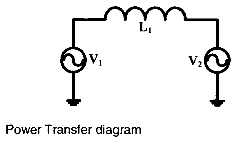
[0031]FIG. 1 is a well-known diagram in Power Systems and is used to describe how power is transferred from a generator to another generator or load. The first generator has an output voltage V1 and is connected to the second voltage V2 through an inductor L1. If the phase angle between V1 and V2 is α then the power transferred is given by

P=V1V2sin(α)X

[0032]Where X is the reactance of inductor L1 at the frequency of operation. This is a generic formula using symbols common in Power Systems analysis.

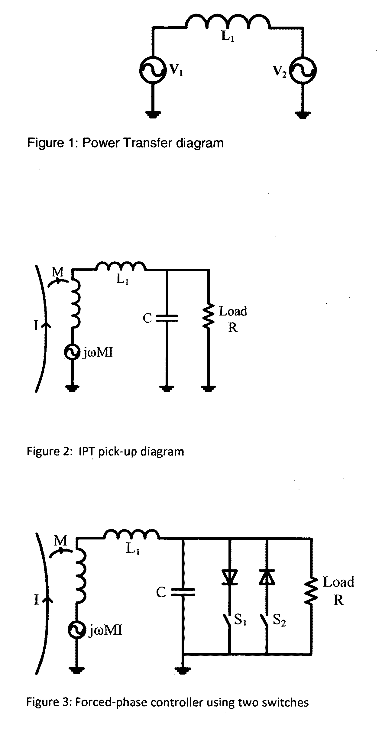
[0033]In an IPT system this same diagram may be interpreted slightly differently as shown in the circuit of FIG. 2. In this case V1 is the voltage induced in the pick-up coil L1 by a current flowing through an IPT track. Thus V1=jωMI where I is the track current. V2 is now the voltage across the tuning capacitor, C, and is the resonant voltage in the IPT system. L1 and C comprise a parallel resonant circuit. In all usual circumstances the phase angle {acute over (α)}, the angle between V1...


PUM


Abstract

An Inductive Power Transfer System pickup provides a controlled AC power supply by controlled variation of the phase angle between the pickup coil induced voltage (jwMI) and the tuning capacitor C voltage. The phase angle can be varied by maintaining the tuning capacitor C voltage substantially constant for a selected time period. Switches S1 and S2 may be used to clamp the tuning capacitor C voltage at substantially zero volts during the selected time period. Switch S1 can be operated to prevent a rise in positive voltage across the tuning capacitor, and switch S2 can be used to prevent the voltage across the tuning capacitor from going negative.

Description

FIELD OF THE INVENTION[0001]This invention relates to Inductive Power Transfer (IPT) and has particular, but not sole, application to the provision of an AC power source. The invention may also be used to provide a DC power source.BACKGROUND[0002]IPT systems are now widely used in industry and elsewhere to couple power from one reference frame to another without physical contact. An example of such a system is described in U.S. Pat. No. 5,293,308, the contents of which are incorporated herein by reference. Wherever such systems are used the method for controlling the power transferred always involves a rectification stage so that the actual output from an IPT system is a controlled DC voltage to which consumer loads may be connected. If, for example, the consumer required an AC source of power then the IPT system would be used to drive an inverter and the output of that inverter would be used to drive the consumer's load. In these circumstances there are several power transfer stage...

Claims


Application Information

Patent Timeline
IPC IPC(8): H01F38/14
CPCH02M3/33576H02J5/005H02J50/12Y02T10/70Y02T10/7072Y02T90/14H03J3/22H04B5/0093H04B5/0037H04B5/0075
Inventor BOYS, JOHN TALBOT
Owner AUCKLAND UNISERVICES LTD
Why Eureka
Try Eureka