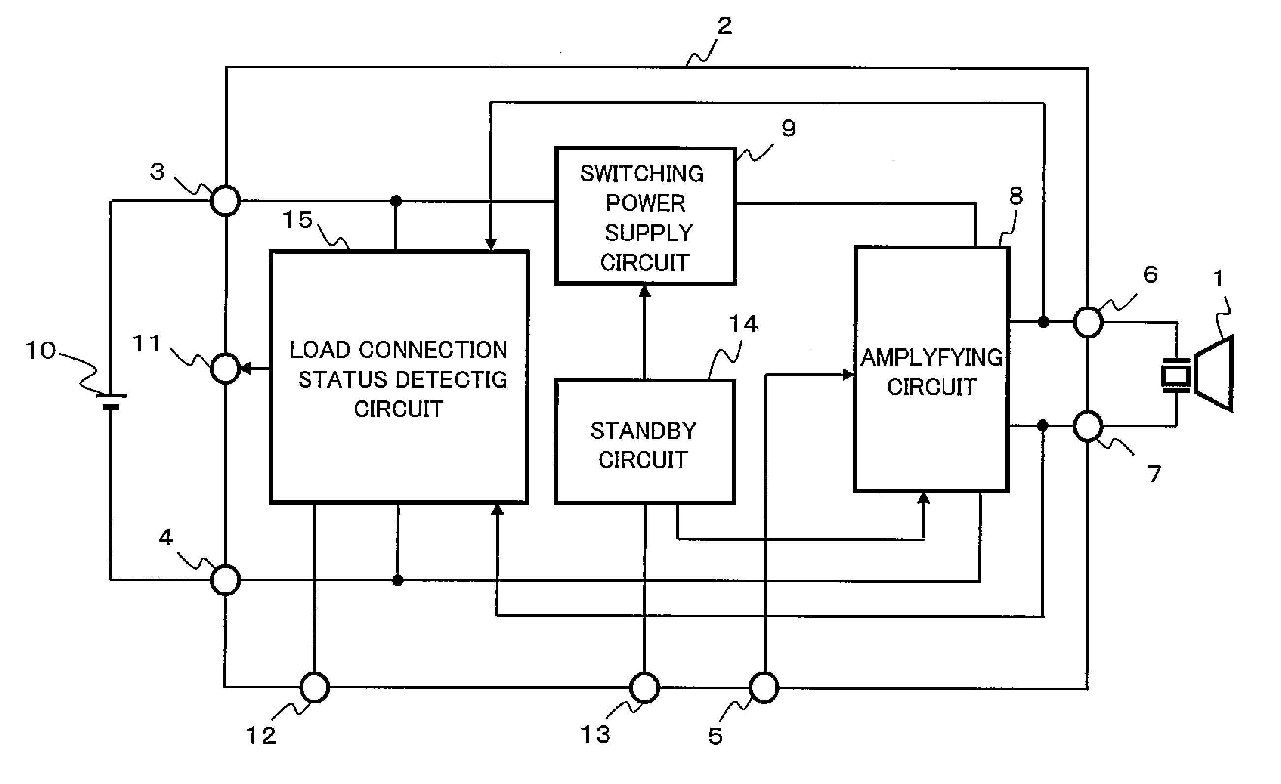
Speaker drive integrated circuit
a technology of integrated circuits and speakers, applied in the direction of stereophonic circuit arrangements, low frequency amplifiers, electrical transducers, etc., can solve problems such as user inability to easily recognize, and achieve the effect of reducing size and weight, mounting area, and cos
- Summary
- Abstract
- Description
- Claims
- Application Information
AI Technical Summary
Benefits of technology
Problems solved by technology
Method used
Image
Examples
embodiment 1
[0039]Configuration of Sound System
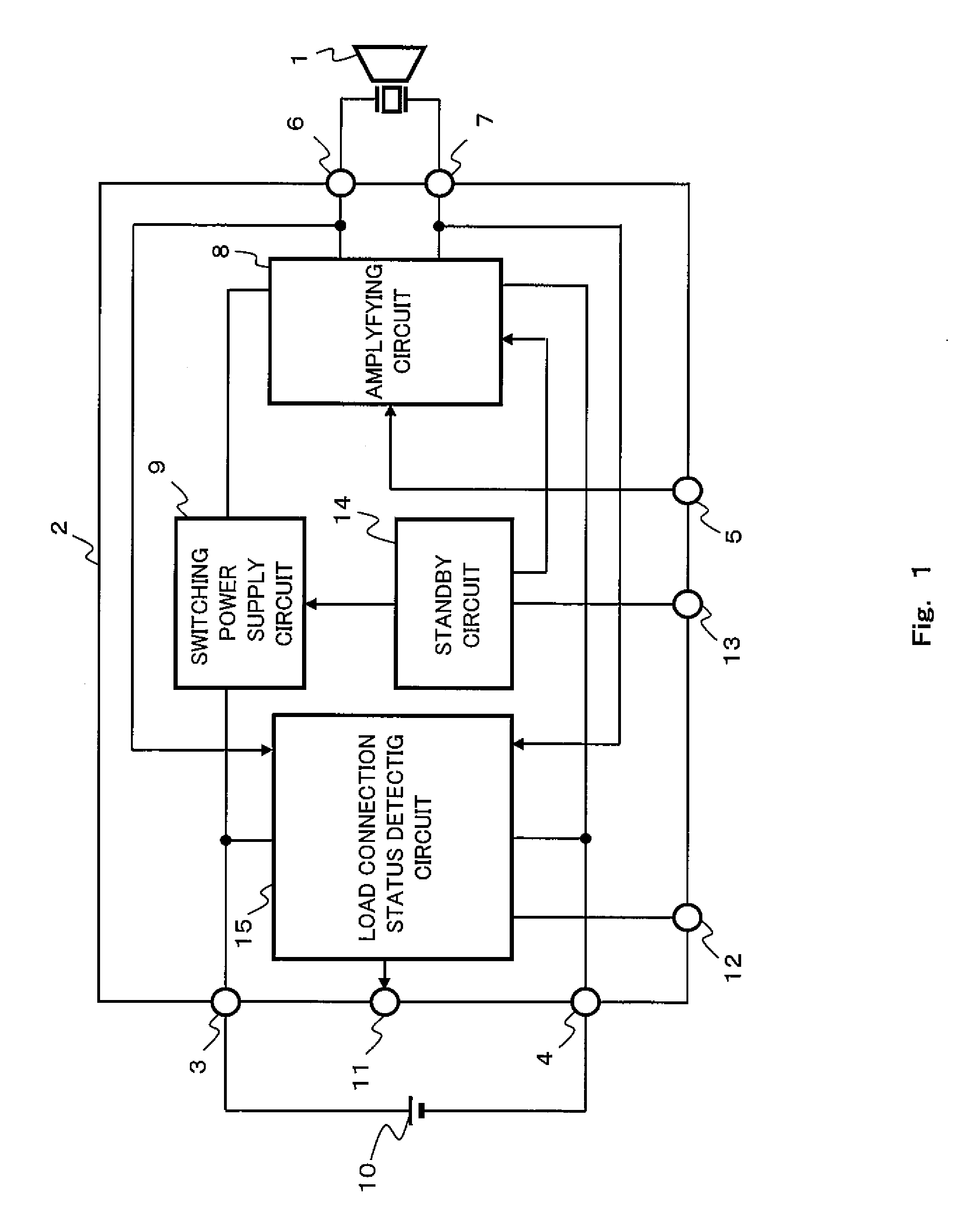
[0040]FIG. 1 is a diagram showing the configuration of a sound system using a speaker drive integrated circuit according to Embodiment 1 of the present invention. The sound system shown in FIG. 1 is one example of a mobile device with a speaker, such as a digital video camera, a digital still camera, a mobile phone, a notebook computer, or a fire alarm.
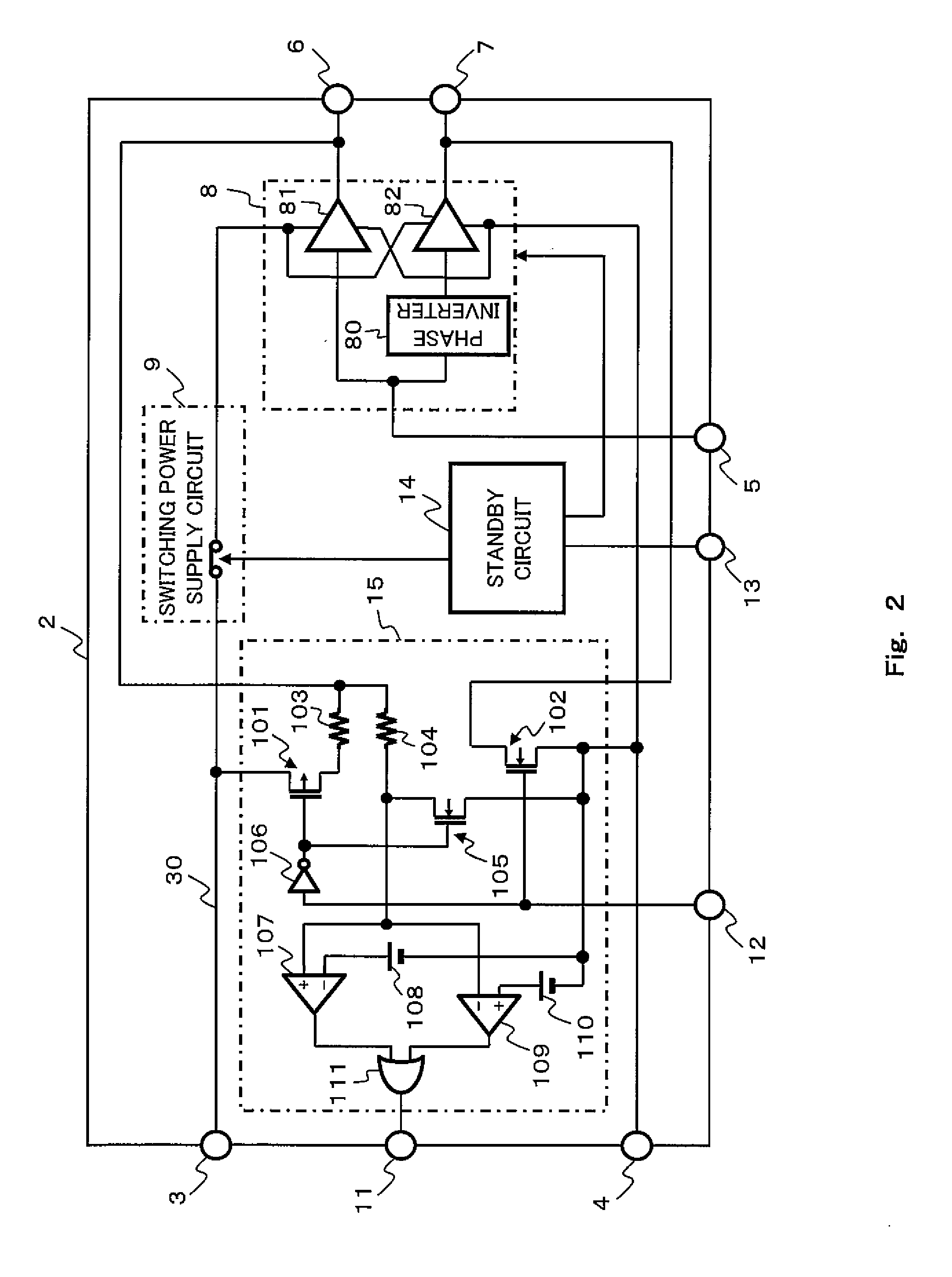
[0041]A speaker drive integrated circuit 2 operates using an external power supply 10, such as a lithium ion battery, as a power supply. The speaker drive integrated circuit 2 amplifies an audio signal input to an input terminal 5 to drive a speaker 1, such as a piezoelectric speaker. To realize such function, the speaker drive integrated circuit 2 includes an amplifying circuit 8, a switching power supply circuit 9, a standby circuit 14, and a load connection status detecting circuit 15. The speaker drive integrated circuit 2 includes, as its own terminals, a power supply terminal 3 and GND terminal...
modification example
[0081]The speaker drive integrated circuit 2 may be a hybrid integrated circuit constituted by replacing a part or all of the MOS transistors constituting the speaker drive integrated circuit 2 with bipolar transistors.
[0082]A NOR gate may be used instead of the OR gate 111. In this case, needless to say, the waveform of the output voltage V11 of the load connection status detecting circuit 15 shown in FIGS. 3A to 3C inverts.
[0083]A below-described clamp circuit 17 may be used instead of the NMOS transistor 105 as the protection circuit for the open detecting comparator 107 and the short detecting comparator 109.
[0084]The operating period of the load connection status detecting circuit 15 is set by applying the start-up voltage V12 of the high level to the start-up terminal 12 (active high) but may be set by applying the start-up voltage V12 of the low level to the start-up terminal 12 (active low).
[0085]The output voltage V11 of the load connection status detecting circuit 15 is ou...
embodiment 2
[0092]Configuration of Sound System
[0093]FIG. 4 is a diagram showing the configuration of the sound system using the speaker drive integrated circuit according to Embodiment 2 of the present invention.
[0094]The speaker drive integrated circuit 2 according to Embodiment 2 shown in FIG. 4 is different from the speaker drive integrated circuit 2 according to Embodiment 1 shown in FIG. 1 in that the standby terminal 13 and the standby circuit 14 are omitted, and the switch circuit 16 configured to realize the standby state is newly provided. The other components of the speaker drive integrated circuit 2 shown in FIG. 4 are the same as those of the speaker drive integrated circuit 2 shown in FIG. 1.
[0095]In the speaker drive integrated circuit 2 shown in FIG. 4, a terminal exclusively for the switch circuit 16 is not provided. The load connection status detecting circuit 15 and the switch circuit 16 share the start-up terminal 12. To be specific, when the start-up voltage V12 is applied ...
PUM
 Abstract
Description
Claims
Application Information
 - R&D
- Intellectual Property
- Life Sciences
- Materials
- Tech Scout
- Unparalleled Data Quality
- Higher Quality Content
- 60% Fewer Hallucinations
Browse by: Latest US Patents, China's latest patents, Technical Efficacy Thesaurus, Application Domain, Technology Topic, Popular Technical Reports.
© 2025 PatSnap. All rights reserved.Legal|Privacy policy|Modern Slavery Act Transparency Statement|Sitemap|About US| Contact US: help@patsnap.com


