Image forming apparatus and image forming method

Active Publication Date: 2011-09-08
KONICA MINOLTA BUSINESS TECH INC
View PDF3 Cites 6 Cited by
  • Summary
  • Abstract
  • Description
  • Claims
  • Application Information

AI Technical Summary

Benefits of technology

[0016]An object of the present invention is to provide an image forming apparatus in which graininess is enhanced and also a total toner amount is reduced without deteriorating image quality in image formation using toner of high chroma.

Problems solved by technology

However, because the achromatic colors based on only CMY is low in the maximum density, thus a large amount of K is used for acromatic colors of middle and high densities.
Conversely, the achromatic colors can be reproduced by only a simple color of K. However, the boundary between the chromatic color and the achromatic color becomes remarkable when the color is continuously varied from a chromatic color to an achromatic color and graininess becomes remarkable when the achromatic color is expressed only by the simple color of K causing deterioration of image quality.
The high chroma toners can mainly expand the color gamut of colors having high brightness, however, they have a feature that sufficient densities of achromatic colors cannot be obtained even when the CMY toners are blended.
That is, the high chroma toners cannot reproduce colors having low brightness.
That is, when an excessively large amount of toner is put on a paper, the toner melted in a fixing step cannot be removed from a fixing roller, and consequently there occurs a phenomenon that the paper having the toner thereon cannot be separated from the fixing roller and thus the paper is to be twined around the fixing roller.
Once this phenomenon occurs, the apparatus cannot continue the print operation.
However, a phenomenon that graininess in a low density area is deteriorated when a black toner is used in the low density area occurs in the conventional image forming apparatus using the high chroma toners.
The black toner has a large dynamic range of the density and thus the graininess is bad.
Furthermore, when the maximum toner amount limitation acts on pixels in the conventional image forming apparatus using high chroma toners, the image density of the pixels is lowered, and thus required high density is not obtained and image information is also lost, and thus the image quality is degraded.

Method used


Image

  • Image forming apparatus and image forming method
  • Image forming apparatus and image forming method
  • Image forming apparatus and image forming method

Examples


first modification

(First Modification)

[0160]A first modification of the above embodiment will be described with reference to FIG. 6. FIG. 6 shows a CMYKG color converter 230 of this modification.

[0161]According to the structure of the apparatus of this modification, in the image forming apparatus 1 of the above embodiment, the CMYKG color converter 230 shown in FIG. 6 may be provided in place of the CMYKG color converter 130.

[0162]The CMYKG color converter 230 has a CMYG color converter 231. Each of the equivalent neutral density converter 131C and the like of the CMYKG color converter 130 of the above embodiment converts an image signal by using the one-dimensional LUT. On the other hand, the CMYG color converter 231 converts the image signals C, M, Y and K to the image signals Cout, Mout, Yout, Kout and Gout in a lump by using a three-dimensional (3D) LUT. The three-dimensional LUT is one LUT for performing the same conversion processing as all of the processing of the equivalent neutral density co...

second modification

(Second Modification)

[0164]A second modification of the above embodiment will be described with reference to FIGS. 7, 8A and 8B. FIG. 7 shows a CMYKG color converter 330 of this modification.

[0165]According to the structure of the apparatus of this modification, in the image forming apparatus 1 according to the above embodiment, the CMYKG color converter 330 shown in FIG. 7 may be provided in place of the CMYKG color converter 130.

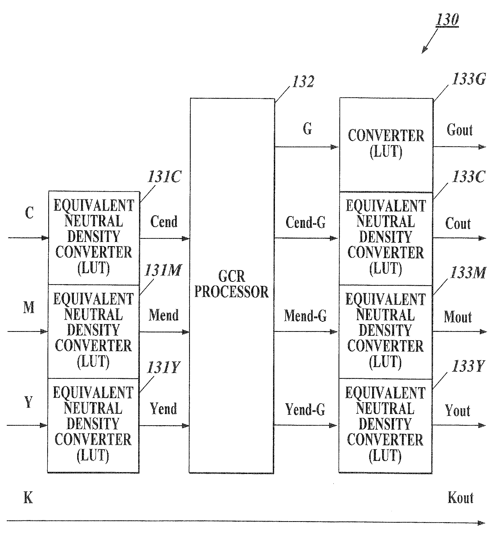
[0166]The CMYKG color converter 330 is obtained by combining the constituent elements of the CMYKG color converter 130 with a structure of separating the K color to K color+gray color. As shown in FIG. 7, the CMYKG color converter 330 has equivalent neutral density converters 131C, 131M and 131Y, a GCR processor 132, equivalent neutral density inverse converters 133C, 133M and 133Y, an calculator 334, an adder 335 and converters 133G and 133K.

[0167]The calculator 334 converts a part of the input image signal K to a gray component to replace the input image...

third modification

(Third Modification)

[0175]A third modification according to the above embodiment will be described with reference to FIG. 9. FIG. 9 shows a CMYKG color converter 430 according to this modification.

[0176]The apparatus of this modification is constructed so as to have a CMYKG color converter 430 shown in FIG. 9 in place of the CMYKG color converter 330 in the image forming apparatus 1 of the second modification.

[0177]The CMYKG color converter 430 has a CMYKG color converter 431, equivalent neutral density inverse converters 133C, 133M and 133Y, and converters 133K and 133G. The CMYKG color converter 431 converts the image signals C, M, Y and K to the image signals Cend-G, Mend-G, Yend-G, Ka and Ga in a lump by using the four-dimensional (4D) LUT. This four-dimensional LUT is one LUT for performing the same conversion processing as all of the processing of the equivalent neutral density converters 131C, 131M and 131Y, the GCR processor 132, the calculator 334 and the adder 335. The fou...


PUM


Abstract

Disclosed is an image forming apparatus including a color converter for converting cyan, magenta and yellow components of a first image signal to equivalent neutral density, calculating a first gray component from cyan, magenta and yellow components of equivalent neutral density, subtracting the first gray component from each of the cyan, magenta and yellow components of equivalent neutral density, subjecting each of the cyan, magenta and yellow components of equivalent neutral density from which the first gray component is subtracted to an inverse conversion of the equivalent neutral density conversion, and outputting a second image signal comprising cyan, magenta and yellow components which are obtained by carrying out the inverse conversion to the cyan, magenta and yellow components of equivalent neutral density from which the first gray component is subtracted, the first black component and the first gray component; an image forming section for forming an image on a paper based on the second image signal by using cyan, magenta, yellow, black and gray toners; and a controller for controlling the color converter and the image forming section.

Description

BACKGROUND OF THE INVENTION[0001]1. Field of the Invention[0002]The present invention relates an image forming apparatus and an image forming method.[0003]2. Description of Related Art[0004]An image forming apparatus such as a copying machine or the like for performing color print has been known. In the color print, four color toners or inks of Y (yellow), M (magenta), C (cyan) and K (black) are used often. For example, color print (image formation) has been performed by using toners of YMCK in an electrophotographic image forming apparatus.[0005]The toner K among the above toners express achromatic colors, however, the achromatic colors can be also expressed by blending the toners of CMY. However, because the achromatic colors based on only CMY is low in the maximum density, thus a large amount of K is used for acromatic colors of middle and high densities. Conversely, the achromatic colors can be reproduced by only a simple color of K. However, the boundary between the chromatic c...

Claims


Application Information

Patent Timeline
IPC IPC(8): G03F3/08
CPCH04N1/6022H04N1/6025H04N1/6027
Inventor SOEDA, KAORIWASHIO, KOJISAWADA, HIDEMASA
Owner KONICA MINOLTA BUSINESS TECH INC
Why Eureka
Try Eureka