
Sprung mass damping control system of vehicle

Active Publication Date: 2011-09-01
TOYOTA JIDOSHA KK
View PDF31 Cites 32 Cited by
  • Summary
  • Abstract
  • Description
  • Claims
  • Application Information

AI Technical Summary

Benefits of technology

[0013]In the sprung mass damping control system as described above, it is preferable that the sprung mass damping controller inhibits execution of the sprung mass damping control or reduce the spring mass damping control amount when upper speed limiting control for limiting the speed of the vehicle to a set upper-limit speed is executed. In this case, the sprung mass damping controller may inhibit execution of the sprung mass damping control when the speed of the vehicle is equal to or higher than a specified speed. Also, the sprung mass damping controller may reduce the sprung mass damping control amount as the vehicle speed increases, when the speed of the vehicle is equal to or higher than the specified speed.

Problems solved by technology

In the meantime, the sprung mass damping control is not necessarily executed in accordance with occurrence of sprung mass vibrations whenever sprung mass vibrations occur in the vehicle body.
Also, the sprung mass damping control may not be correctly carried out, depending on status conditions or running conditions of the vehicle.

Method used


Image

  • Sprung mass damping control system of vehicle
  • Sprung mass damping control system of vehicle
  • Sprung mass damping control system of vehicle

Examples


first embodiment

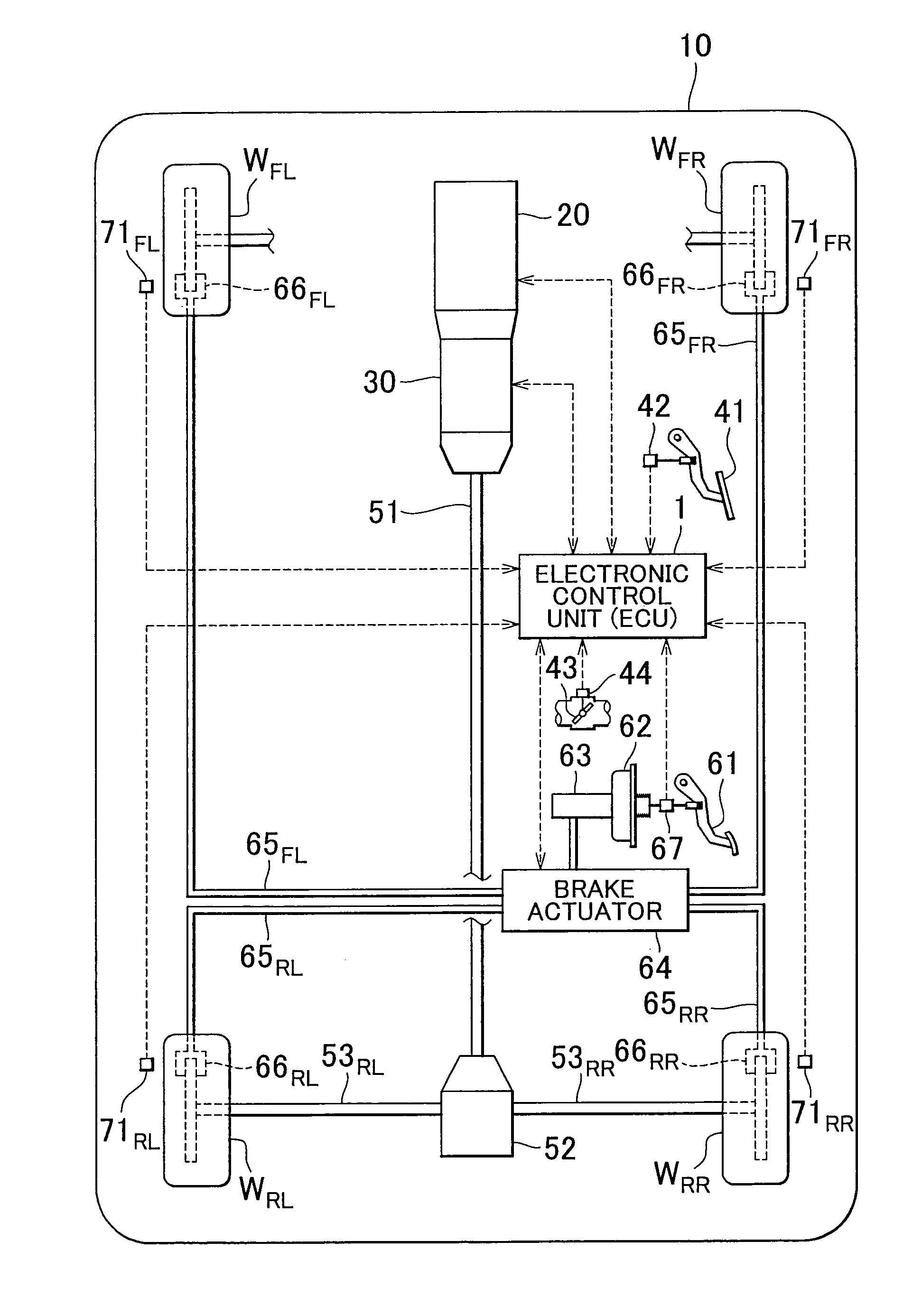
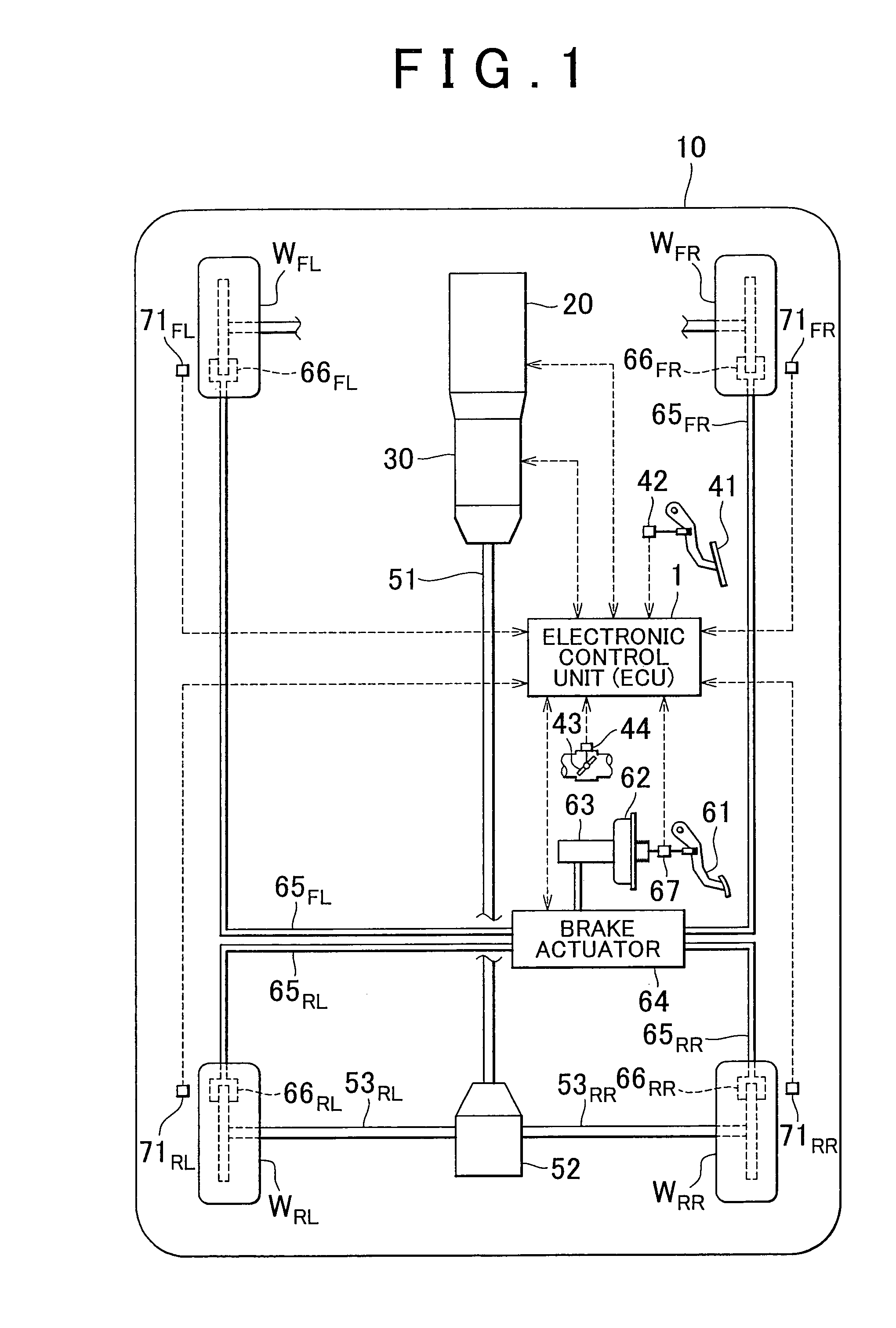
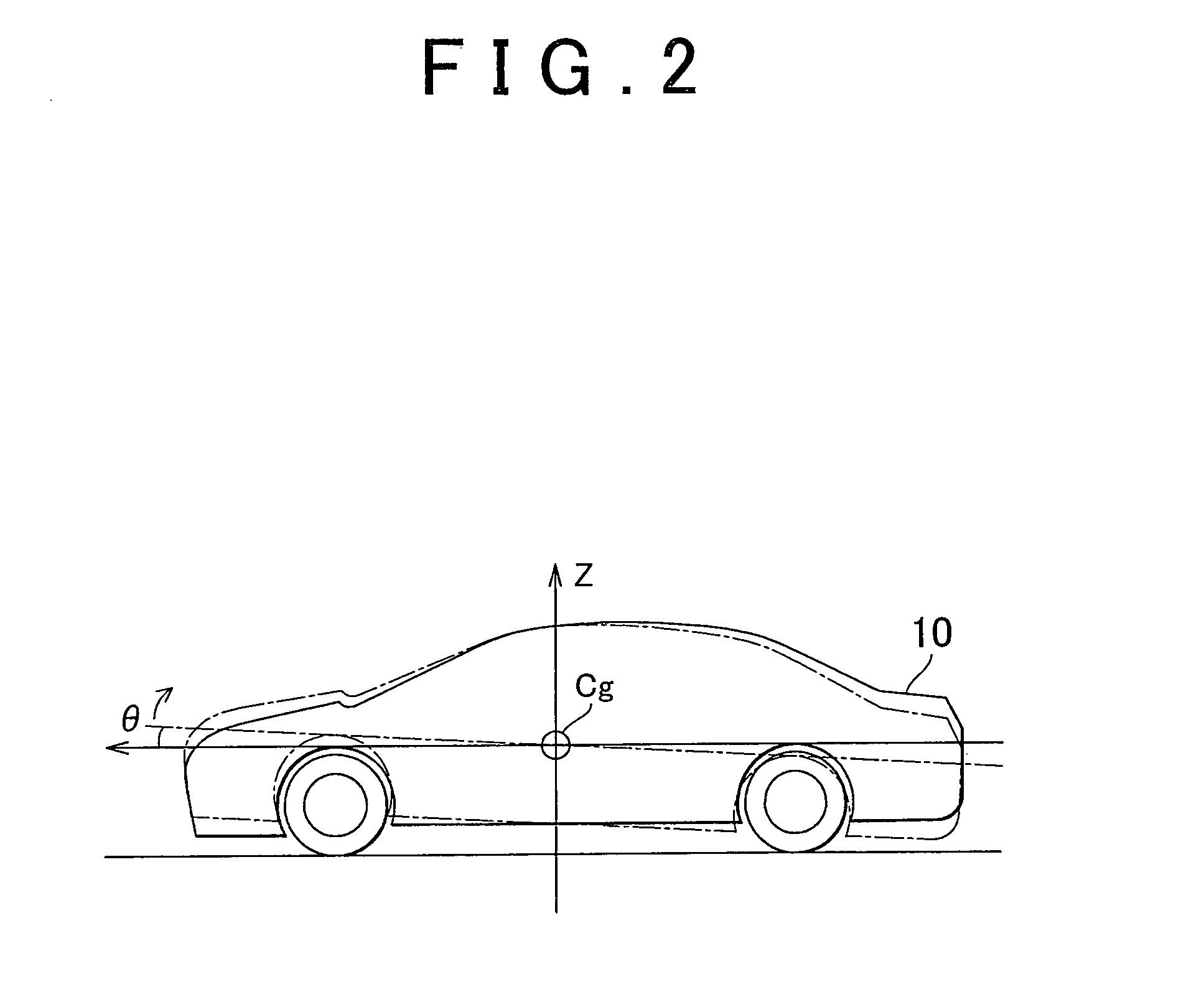
[0028]A sprung mass damping control system of a vehicle according to the invention will be described with reference to FIG. 1 to FIG. 5.

[0029]The sprung mass damping control system of the first embodiment is prepared as one function of an electronic control unit (ECU) 1 as shown in FIG. 1. The electronic control unit 1 consists principally of CPU (Central Processing Unit), ROM (Read-Only Memory) in which certain control programs, and the like, are stored in advance, RAM (Random Access Memory) that temporarily stores the results of computations of the CPU, back-up RAM that stores information prepared in advance, etc., which are not illustrated in FIG. 1.

[0030]FIG. 1 illustrates an example of vehicle 10 in which the sprung mass damping control system of this embodiment is used. The vehicle 10 illustrated in FIG. 1 is, for example, a FR (front-engine rear-drive) vehicle that transmits power output (output torque) from a power source at the front side of the vehicle to driving wheels WR...

second embodiment

[0110]The vehicle 10 of the second embodiment is equipped with an upper speed limiting control system for running the vehicle while limiting the vehicle speed to a set upper-limit speed, and the electronic control unit 1 that provides the upper speed limiting control system includes an upper speed limiting controller that implements upper speed limiting control. The upper speed limiting control refers to control for reducing the speed of the vehicle 10 by putting a restriction on the final driver-requested torque when the speed of the vehicle 10 exceeds a specified speed that is a little lower than the set upper-limit speed, for example, so that the speed of the vehicle 10 does not exceed the set upper-limit speed. More specifically, the upper speed limiting control refers to control (so-called speed limiter control) for setting the maximum vehicle speed as the set upper-limit speed in advance, and controlling the vehicle 10 so that its speed does not exceed the maximum speed. The u...


PUM


Abstract

A sprung mass damping control system of a vehicle is provided. The sprung mass damping control system includes a sprung mass damping controller that sets a sprung mass damping control amount for damping sprung mass vibrations that occur in a vehicle body in response to an input from a road or a driver-requested torque, and a drive controller that controls an output of a vehicle drive unit so as to achieve the sprung mass damping control amount, thereby to execute sprung mass damping control. The drive controller is configured to permit or inhibit execution of the sprung mass damping control according to at least one of operating conditions of the vehicle, status conditions of the vehicle and driver's requests.

Description

INCORPORATION BY REFERENCE[0001]The disclosure of Japanese Patent Applications No. 2008-282514, filed on Oct. 31, 2008, and No. 2009-035557, filed on Feb. 18, 2009, including their specifications, drawings and abstracts, are incorporated herein by reference in their entirety.BACKGROUND OF THE INVENTION[0002]1. Field of the Invention[0003]The invention relates to a sprung mass damping control system of a vehicle for damping sprung mass vibrations that occur in the vehicle body.[0004]2. Description of the Related Art[0005]There is known a technology, called sprung mass damping control, for damping or suppressing sprung mass vibrations that occur in the vehicle body by utilizing suitable vibration damping means. For example, a technology of controlling the driving force of the vehicle in order to damp sprung mass vibrations of the vehicle is described in Japanese Patent Application Publication No. 2006-69472 (JP-A-2006-69472). According to JP-A-2006-69472, the driving force is controll...

Claims


Application Information

Patent Timeline
IPC IPC(8): B60W30/02G06F19/00B60W10/22B60W10/04B60W10/06B60W10/10B60W30/00F02D29/00F16F15/02
CPCB60W10/06B60W10/11B60W10/184B60W30/025B60W30/20B60W2520/10F02D2200/0404B60W2520/28B60W2540/10B60W2540/12B60W2710/105B60W2720/16B60W2520/16F02D11/105
Inventor ITABASHI, KAIJIKINOSHITA, GOHKI
Owner TOYOTA JIDOSHA KK
Learn More