
System and method for performing in-service optical fiber network certification

Active Publication Date: 2011-09-01
SOTO ALEXANDER I +1
View PDF24 Cites 101 Cited by
  • Summary
  • Abstract
  • Description
  • Claims
  • Application Information

AI Technical Summary

Benefits of technology

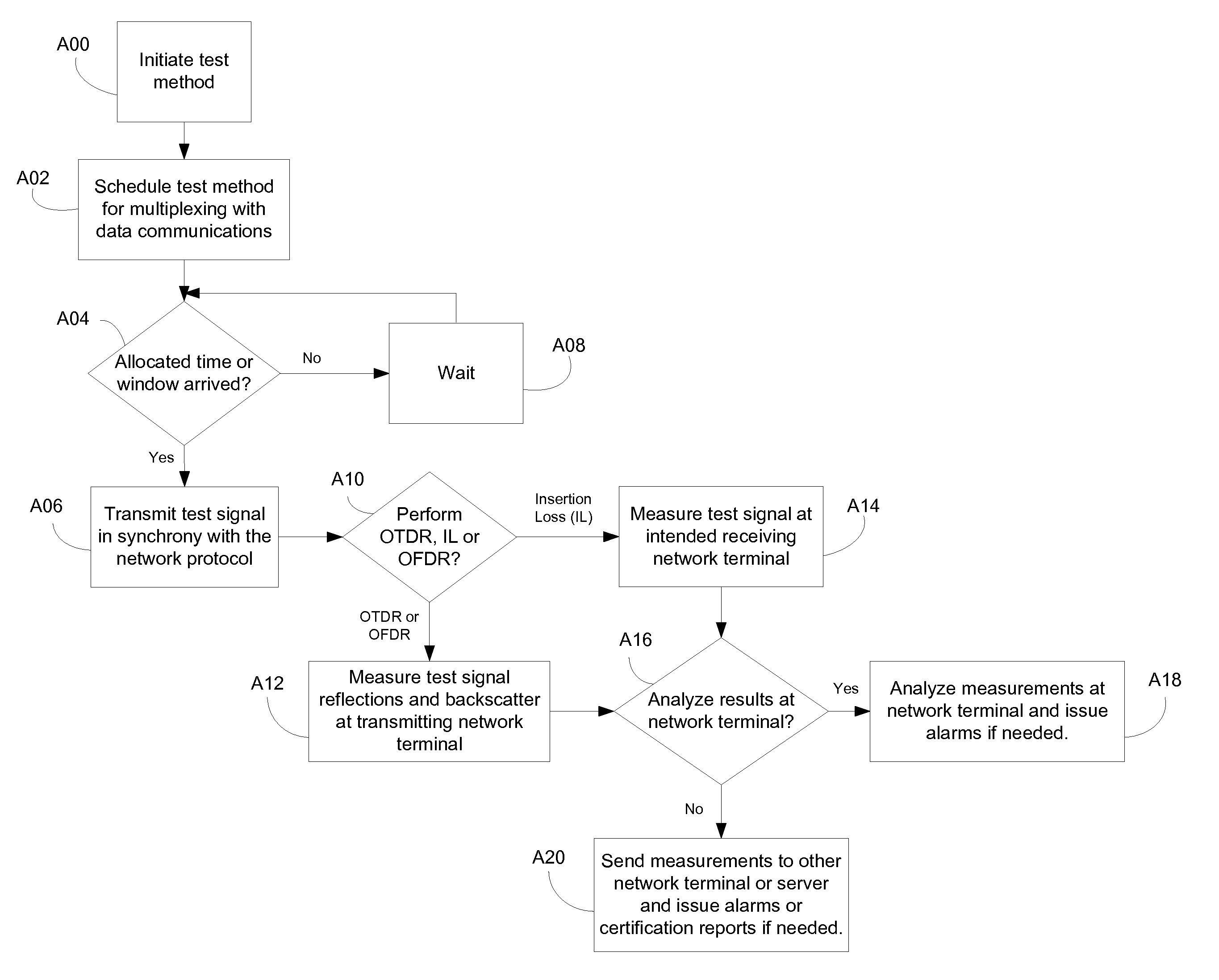
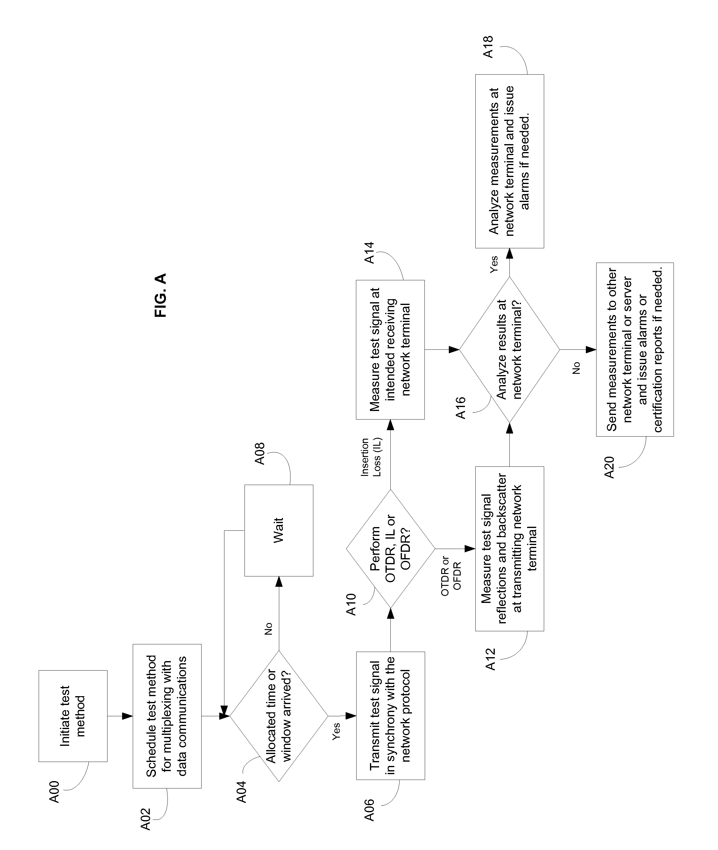
[0045]In one aspect of an embodiment of the invention the PMA layer can control the PMD layer and control the timing of test methods and receive results of test methods.

Problems solved by technology

The labor and material costs for troubleshooting and diagnosing maintenance or service outage problems within an optical fiber network can dominate an Operator's operating budgets and impact customer's SLAs negatively.
This places extra cost burden on the fiber plants to provide field testability.
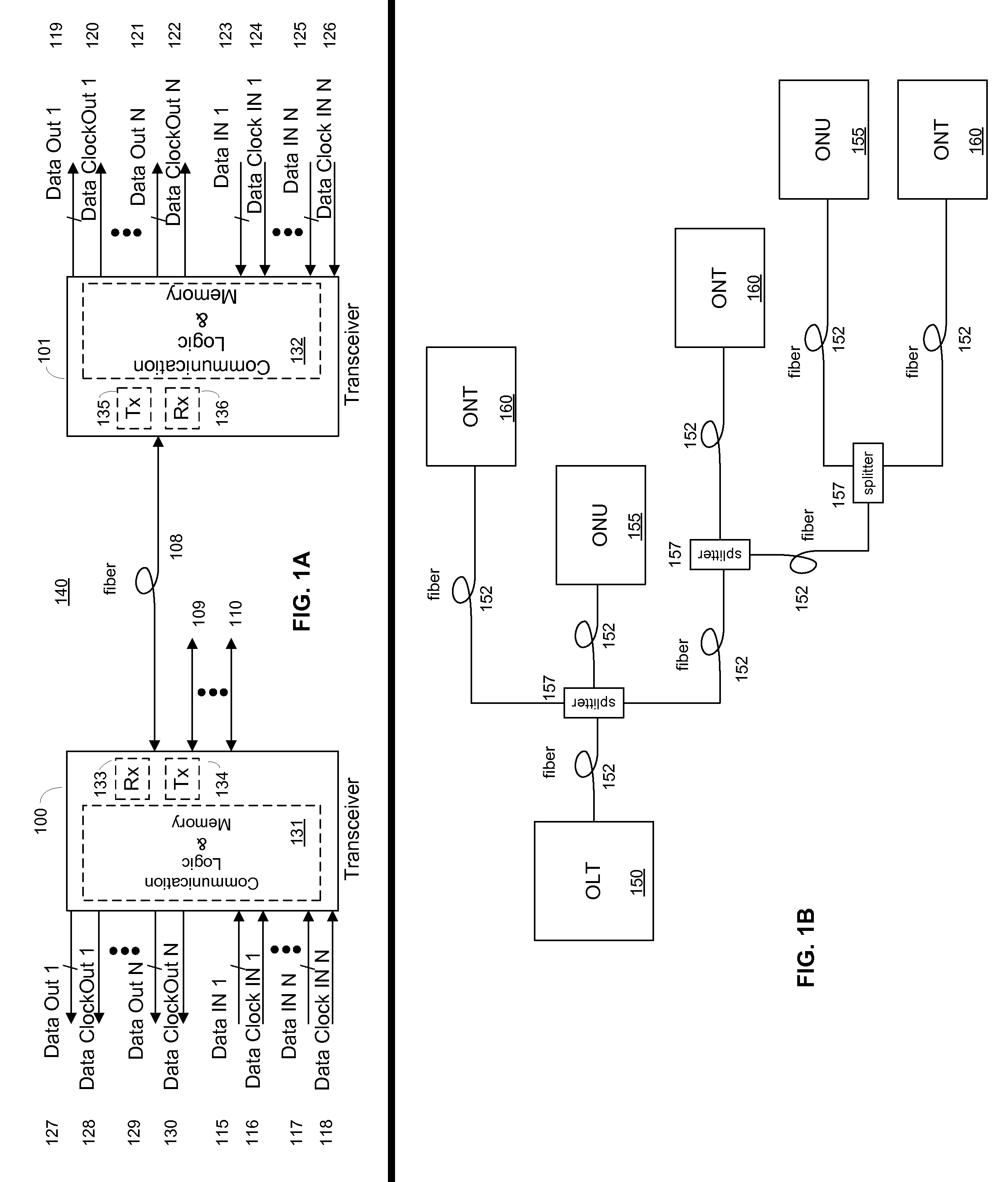
Each additional splitter not only means more capital expense (CapEx) is incurred by the Operator but it also takes away precious dBs from the optical link budget.
This is a capital and labor intensive method for routine fiber maintenance checks while ensuring service outages do not occur.

Method used


Image

  • System and method for performing in-service optical fiber network certification
  • System and method for performing in-service optical fiber network certification
  • System and method for performing in-service optical fiber network certification

Examples


Embodiment Construction

[0085]Reference will now be made in detail to various embodiments of the invention, examples of which are illustrated in the accompanying drawings. While the invention will be described in conjunction with these embodiments, it will be understood that they are not intended to limit the invention to these embodiments. On the contrary, the invention is intended to cover alternatives, modifications and equivalents, which may be included within the spirit and scope of the invention as defined by the appended claims. Furthermore, in the following description of the present invention, numerous specific details are set forth in order to provide a thorough understanding of the present invention. In other instances, well-known methods, procedures, components, and circuits have not been described in detail as not to unnecessarily obscure aspects of the present invention.

[0086]The method and system of the present invention can coexist with existing network protocols or be engineered into futur...


PUM


Abstract

A system and method for performing an in-service optical time domain reflectometry test, an in-service insertion loss test, and an in-service optical frequency domain reflectometry test using a same wavelength as the network communications for point-to-point or point-to-multipoint optical fiber networks while maintaining continuity of network communications are disclosed.

Description

CROSS-REFERENCES TO RELATED APPLICATIONS[0001]This application is filed under 37 C.F.R. §1.53(b) as a continuation-in-part claiming the benefit under 35 U.S.C §120 of the pending U.S. patent application Ser. No. 12 / 233,495, “System and Method for Performing In-Service Fiber Optic Network Certification”, which was filed by the same inventors on Sep. 18, 2008 claiming the benefit under 37 C.F.R. §1.53(b) of U.S. patent application Ser. No. 10 / 793,546 filed on Mar. 3, 2004 by the same inventors and now issued as U.S. Pat. No. 7,428,382 on Sep. 23, 2008, which claims the benefit under 35 U.S.C. 119(e) of U.S. Provisional Application No. 60 / 451,614, filed Mar. 3, 2003, now expired, and entirely incorporated herein by reference.FIELD OF THE INVENTION[0002]The invention relates generally to optical fiber communication networks, and more specifically to the network certification, diagnostic testing, and optical measurement of an optical fiber network.BACKGROUND OF THE INVENTION[0003]Trouble...

Claims


Application Information

Patent Timeline
IPC IPC(8): H04B17/00
CPCH04B10/071H04J14/02H04J14/0226H04J14/0279H04J14/0282H04J14/0275H04J14/0252H04J14/0256H04J14/0257H04J14/0267H04J14/0273H04J14/0247
Inventor SOTO, ALEXANDER I.SOTO, WALTER G.
Owner SOTO ALEXANDER I
Learn More