
Freestanding carbon nanotube networks based temperature sensor

a carbon nanotube and temperature sensor technology, applied in nanotechnology, photovoltaics, electrical/magnetic means, etc., can solve the problems of reduced scalability, non-negligent power consumption, and high cost, and achieve the effect of reducing the possibility of disturbing the neighbouring environment and easy shrinkag

Inactive Publication Date: 2011-09-01
UNIV DEGLI STUDI DI PARMA
View PDF3 Cites 15 Cited by
  • Summary
  • Abstract
  • Description
  • Claims
  • Application Information

AI Technical Summary

Benefits of technology

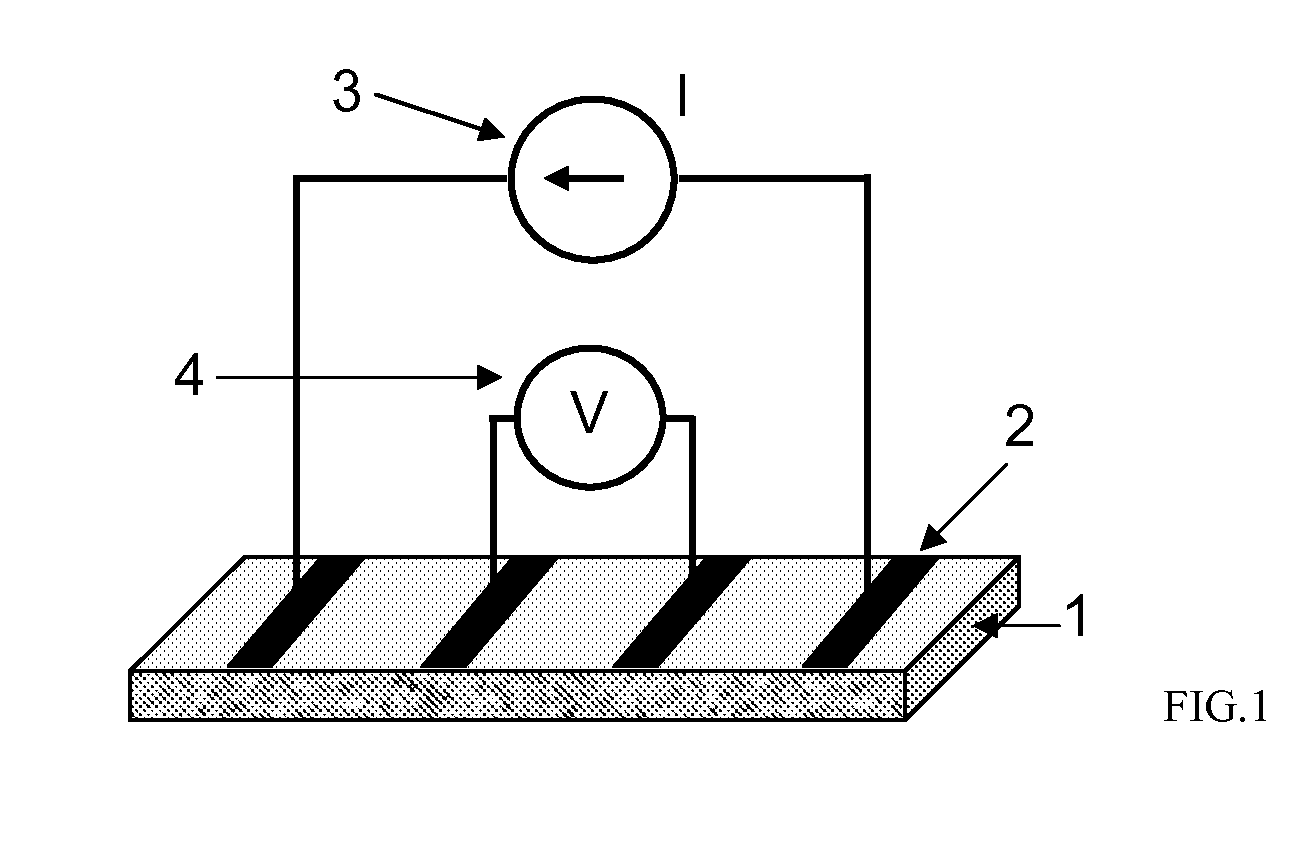
[0002]The present invention introduces a small-size temperature sensor, which exploits a random or oriented network of un-functionalized, single or multi-walled, carbon nanotubes to monitor a wide range of temperatures. Such network is manufactured in the form of freestanding thin film with an electric conductance proven to be a monotonic function of the temperature, above 4.2 K. Said carbon nanotube film is wire-connected to a high precision source-measurement unit, which measures its electric conductance by a standard two or four-probe technique. Said temperature sensor has a low power consumption, an excellent stability and durability, a high sensitivity and a fast response; its manufacturing method is simple and robust and yields low-cost devices. Said temperature sensor, freely scalable in dimension, is suitable for local accurate measurements of rapidly and widely changing temperatures, while introducing a negligible disturb to the measurement environment.

Problems solved by technology

Commercial solid-state temperature sensors have several limitations, the main ones being the limited range of operation, the reduced scalability, the non negligible power consumption and the high cost.
Temperature measurements in small size systems require miniaturized sensors with very limited perturbing effects and very high speed.
Major obstacles presently preventing carbon nanotube commercial implementation in new classes of electronic devices and sensors are the care needed for their production, the lack of a technique for their assembly with precisely controlled positioning and orientation as well as the impossibility to control their chirality and diameter.

Method used


Image

  • Freestanding carbon nanotube networks based temperature sensor
  • Freestanding carbon nanotube networks based temperature sensor
  • Freestanding carbon nanotube networks based temperature sensor

Examples


example 1

High Carbon Conversion Synthesis of MWCNT

[0054]The experimental plant for CNT syntheses consists of three sections: feed section, reaction section, analysis section. All the gas pipes (¼″ De) are of Teflon, connections and two, three and four way valves in stainless steel, to avoid any corrosion due to the presence of water in the reaction products.

[0055]The feed section allows the feeding with one or more hydrocarbons as source and uses N2 as carrier gas. For each gas a mass flow controller is used, in order to assure a constant flow rate. The reaction section allows the preparation of carbon nanotubes in a reactor, consisting of a quartz tube of 300 mm length and 16 mm internal diameter. A quartz reactor, placed in a vertical furnace, is filled with a thin layer of catalyst particles that is crossed perpendicularly by the gaseous feed. An external quartz tube, internal diameter 35 mm, permitted the preheating of the reactants stream. In order to measure the temperature inside the ...

example 2

MWCNT Films Fabrication and Their Characterisation

[0061]To remove catalyst impurities, the grown MWCNTs are treated with 46% HF aqueous solution; a solid residue is afterwards extracted and washed with distilled water, then centrifuged and finally dried at 353 K for 12 h.

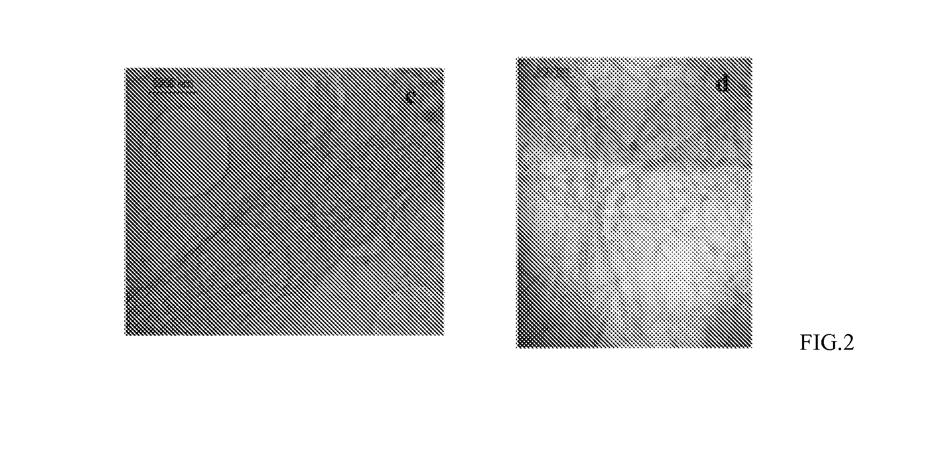
[0062]The final product is an sample of high purity MWCNTs, with a length in the range 100-200 μm and internal and external diameter of 10-30 nm and 5-10 nm, respectively (a TEM image of the MWCNTs is shown in FIG. 2).

[0063]The MWCNTs are used to fabricate random networks (MWCNTNs) in the form of thin films, with a fabrication procedure described below (FIG. 4):

[0064]9. 0.5 g of MWCNTs are suspended in 100 g of water in presence of 0.1 mg of sodium dodecyl sulfate and sonicated for 15 min

[0065]10. the solution is then vacuum filtered onto a membrane support

[0066]11. after drying, MWCNT films of different thicknesses and densities are removed from the support.

[0067]The described MWCNTN preparation procedure does not ...

example 3

Manufacturing of CNT T-sensor

[0068]The so-obtained MWCNTNs (FIG. 5), typically with thickness of 100-300 um and diameter of 1-4 cm, can be folded and cut and are sufficiently robust to let stable contacts (by metal evaporation or, in a simplified embodiment, silver paint) to be formed and to withstand sudden and long thermal stresses. 4 metallic pads (contacts) are created with electrically conductive Ag paste, on samples of dimensions 2×6 mm2 of MWCNTN, with thickness in the range 200-300 m to allow a precise measurement of the conductance. Due to the metallic nature of MWCNTs, the nanotube networks can be highly conductive and a 4-probe method is necessary to accurately measure their resistance, by overcoming the problem of a comparatively non-negligible contact resistance (FIG. 6).


PUM


Abstract

The present invention introduces a small-size temperature sensor, which exploits a random or oriented network of un-functionalized, single or multi-walled, carbon nanotubes to monitor a wide range of temperatures. Such network is manufactured in the form of freestanding thin film with an electric conductance proven to be a monotonic function of the temperature, above 4.2 K. Said carbon nanotube film is wire-connected to a high precision source-measurement unit, which measures its electric conductance by a standard two or four-probe technique. Said temperature sensor has a low power consumption, an excellent stability and durability, a high sensitivity and a fast response; its manufacturing method is simple and robust and yields low-cost devices. Said temperature sensor, freely scalable in dimension, is suitable for local accurate measurements of rapidly and widely changing temperatures, while introducing a negligible disturb to the measurement environment.

Description

FIELD OF THE INVENTION [0001]The present invention relates to carbon nanotubes and in particular to the manufacturing of carbon nanotube networks (CNTNs), in the form of thin films, and their production as sensing elements in small size, low-power consumption, wide-range and fast temperature sensors. The network electric conductance is a stable parameter with a monotonic, non-metallic dependence on the temperature and is suitable to be exploited as the detecting physical quantity in negative temperature coefficient temperature sensors.BRIEF SUMMARY [0002]The present invention introduces a small-size temperature sensor, which exploits a random or oriented network of un-functionalized, single or multi-walled, carbon nanotubes to monitor a wide range of temperatures. Such network is manufactured in the form of freestanding thin film with an electric conductance proven to be a monotonic function of the temperature, above 4.2 K. Said carbon nanotube film is wire-connected to a high preci...

Claims


Application Information

Patent Timeline
IPC IPC(8): H01L29/66C01B31/02C01B31/00H01L21/768B82Y30/00
CPCB82Y15/00G01K2211/00G01K7/226G01K7/186
Inventor ALTAVILLA, CLAUDIABOBBA, FABRIZIOCIAMBELLI, PAOLOCUCOLO, ANNAMARIADI BARTOLOMEO, ANTONIOGIUBILEO, FILIPPOPIANO, SAMANTASANNINO, DIANASARNO, MARIASCARFATO, ALESSANDRO
Owner UNIV DEGLI STUDI DI PARMA
Learn More