
Method and Structure for a Cool Roof by Using a Plenum Structure

a technology of plenum structure and cooling roof, which is applied in the direction of thermal-pv hybrid energy generation, ventilation system, heating type, etc., can solve the problems of mass species extinction, harmful to humans, and increase the rate of warming, so as to improve the operation procedure of solar modules and facilitate use. , the effect of reducing the cos

Inactive Publication Date: 2011-09-01
SUNEDISON INC
View PDF100 Cites 23 Cited by
  • Summary
  • Abstract
  • Description
  • Claims
  • Application Information

AI Technical Summary

Benefits of technology

"The invention is about a method and structure for cooling a roof using a plenum structure that transfers air through a roof. The method involves transferring air with a selected flow rate through the plenum structure, which is coupled to the roof and is designed to cool the roof for a predetermined amount of time. The cooling effect is achieved by maintaining a specific temperature profile on the surface of the roof, which helps to reduce heat transfer to the building and the urban heat island effect. The invention has applications in both industrial and commercial buildings, and can provide a cool roof that improves roof durability and reduces cooling loads."

Problems solved by technology

Obviously, our daily lives depend, for the most part, upon oil or other fossil fuels, which are becoming increasingly scarce.
The increase in temperature is expected to cause extreme weather conditions and a drastic size reduction of the polar ice caps, which in turn will lead to higher sea levels and a further increase in the rate of warming.
Ultimately, effects may include mass species extinctions, and uncertainties that may be detrimental to humans.
Although solar panels have been used successful for certain applications, there are still limitations.
Solar cells are often costly.
Depending upon the geographic region, there may be financial subsidies from governmental entities for purchasing solar panels, which otherwise might not be competitive with the purchase of electricity from public power companies.
Such wafer materials are costly and difficult to manufacture efficiently on a large scale.
Availability of solar panels is also somewhat scarce.
Solar panels are often difficult to find and purchase from limited sources of photovoltaic silicon bearing materials.

Method used


Image

  • Method and Structure for a Cool Roof by Using a Plenum Structure
  • Method and Structure for a Cool Roof by Using a Plenum Structure
  • Method and Structure for a Cool Roof by Using a Plenum Structure

Examples


Embodiment Construction

[0044]The present invention relates to operation of thermal solar system. More particularly, the present invention provides a method and structure for cooling roof by using a plenum structure associating a thermal solar system. Merely, by way of example, the present invention has been applied to a thermal solar module configured on a building structure, but it would be recognized that the invention has a much broader range of applications.

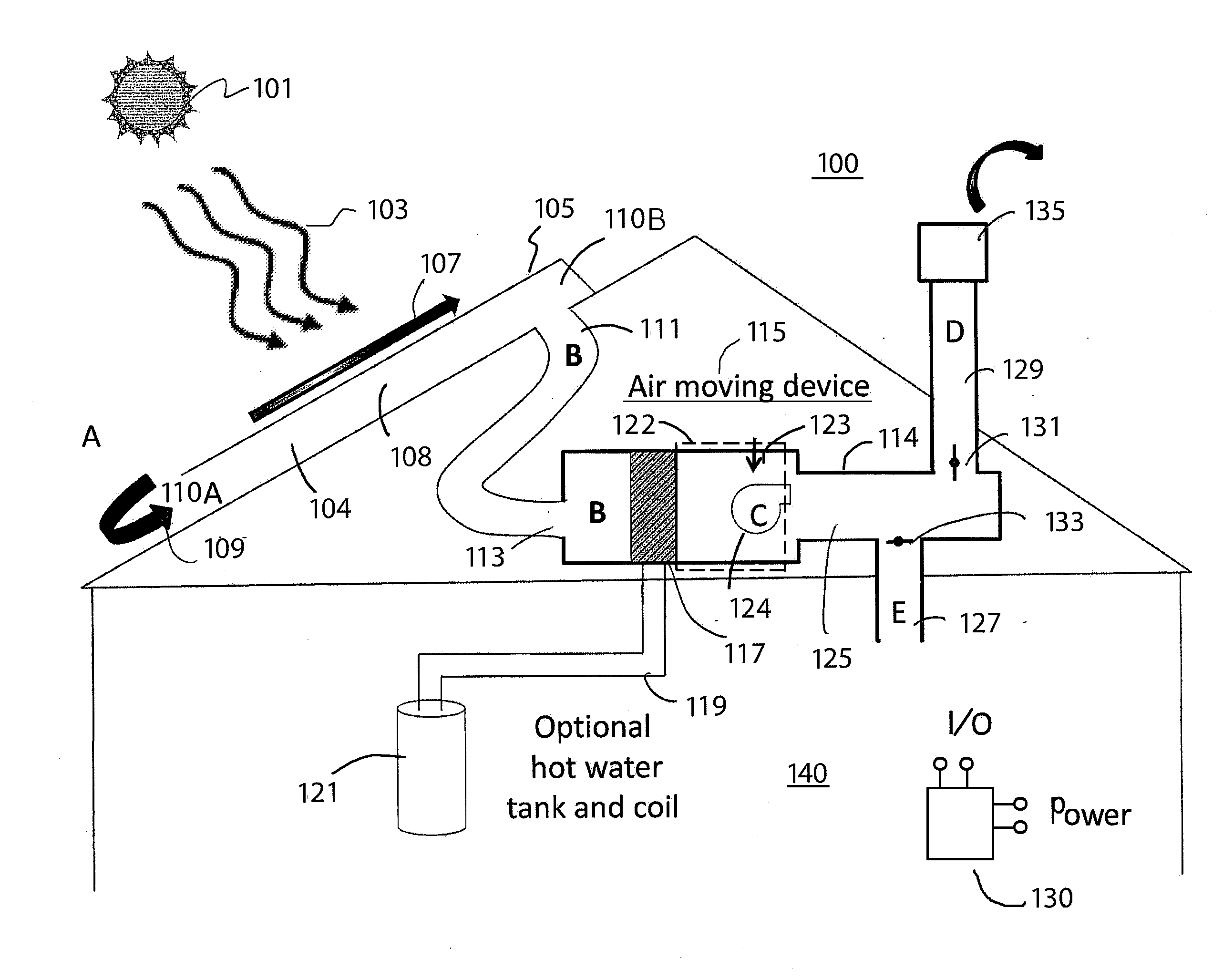
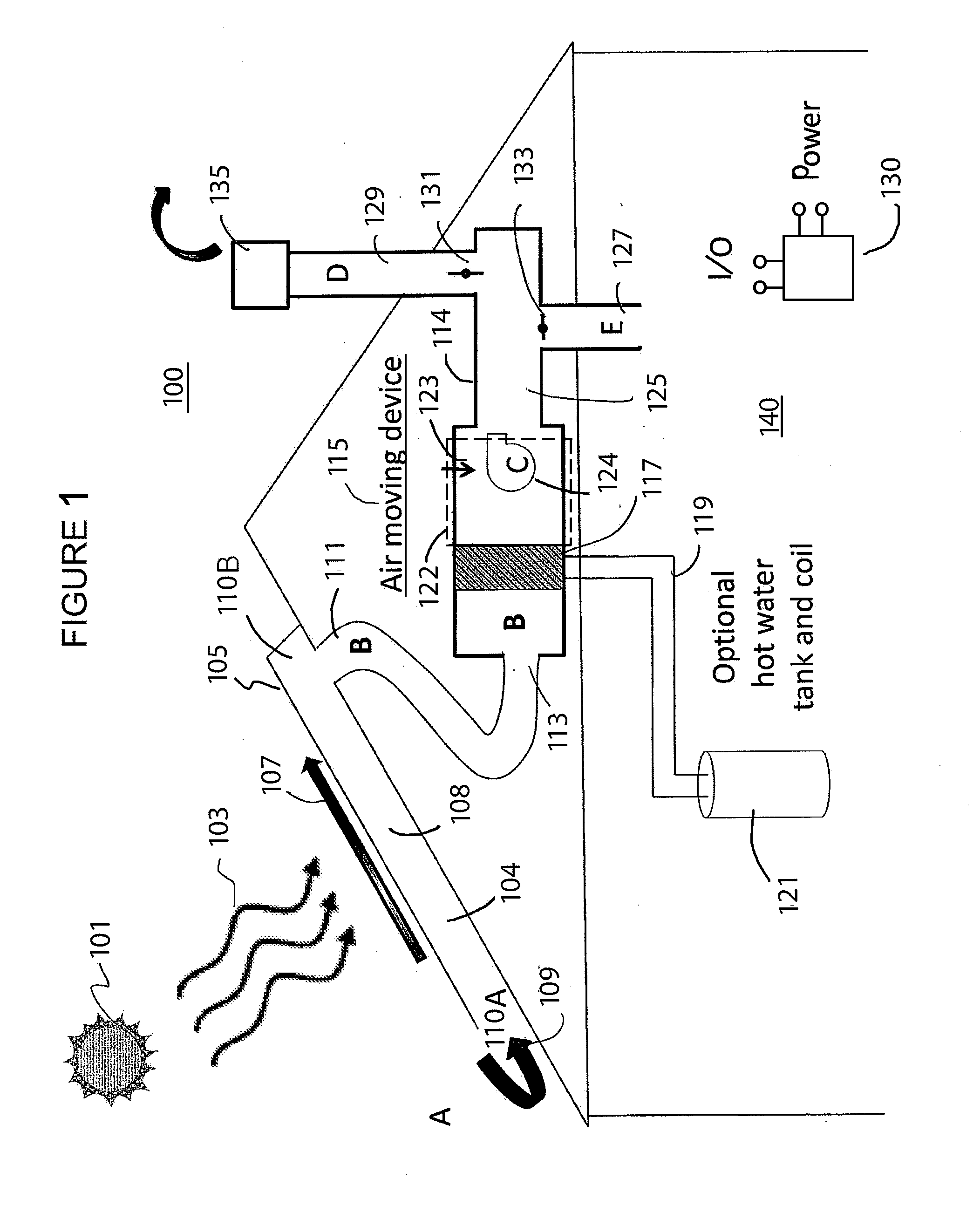
[0045]FIG. 1 is a simplified side view diagram of a thermal solar system according to an embodiment of the present invention. This diagram is merely an example, which should not unduly limit the scope of the claims herein. One of ordinary skill in the art would recognize other variations, modifications, and alternatives. As shown, the thermal solar system 100 includes a plurality of thermal modules spatially configured as an N by M array, where N is an integer equal to or greater than 1, and M is an integer greater than 2 spatially disposed and att...


PUM


Abstract

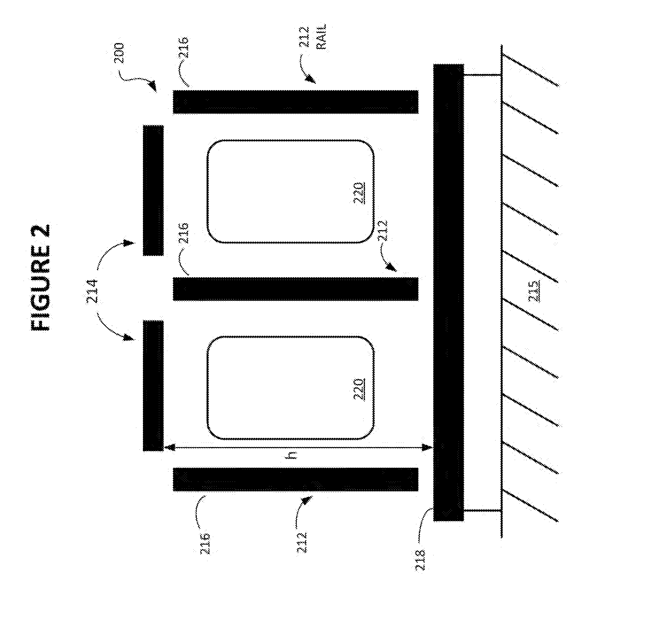
A plenum structure for cooling both a roof and a solar module includes an upper surface comprising at least a portion of a bottom face of a solar module having a length and a width and an under surface comprising a top face of a pan structure disposed a first vertical spacing directly below the upper surface and a second vertical spacing above the roof. The plenum structure includes a first side face and a second side face respectively coupled to the upper surface and the under surface, a first end face and a second end face respectively coupled to upper surface, the under surface, the first side face, and the second side face to enclose a spatial volume defined by the length, the width, and the first vertical spacing.

Description

CROSS-REFERENCE TO RELATED APPLICATION[0001]This application is a continuation in part application of U.S. patent application Ser. No. 12 / 794,352, filed Jun. 4, 2010, entitled “A METHOD AND STRUCTURE FOR A COOL ROOF BY USING A PLENUM STRUCTURE” by inventor Ramachandran Narayanamurthy, commonly assigned and incorporated by reference herein for all purposes.BACKGROUND OF THE INVENTION[0002]This invention relates to operation of thermal solar systems, and in particular to a method and structure for cooling a roof by using a plenum structure associated with a thermal solar system. The invention has been applied to a thermal solar module on a building structure, but it will be recognized that the invention has a much broader range of applications.[0003]Over the past centuries, the world population has grown rapidly. Along with the population, demand for resources has also grown. Such resources include raw materials such as wood, iron, and copper, and include energy, such as fossil fuels ...

Claims


Application Information

Patent Timeline
Patent Type & Authority Applications(United States)
IPC IPC(8): H01L31/052F24F7/02
CPCF24D11/003H02S40/44F24F5/0096F24F7/025F24F2005/0064H01L31/0521Y02B10/12Y02B10/20Y02B10/24Y02B10/70Y02E10/50Y02E10/60H02S20/23H02S20/00F24F5/0046H02S40/42Y02A30/272Y02B10/10
Inventor NARAYANAMURTHY, RAMACHANDRAN
Owner SUNEDISON INC
Learn More