Combustion systems and power plants incorporating parallel carbon dioxide capture and sweep-based membrane separation units to remove carbon dioxide from combustion gases
a technology of combustion gas and carbon dioxide capture, which is applied in the direction of machine/engine, separation process, lighting and heating apparatus, etc., can solve the problems of power plants generating enormous amounts of flue gas, and achieve the effect of reducing the environmental impact of discharging this stream and good carbon dioxide removal
- Summary
- Abstract
- Description
- Claims
- Application Information
AI Technical Summary
Benefits of technology
Problems solved by technology
Method used
Image
Examples
example 1
Bases of Calculations for Other Examples
[0132](a) Membrane permeation experiments: Sets of permeation experiments were performed with two different composite membranes, each having a polyether-based selective layer. The properties of the membranes as measured with a set of pure gases at 6.7 bar absolute and 30° C. are shown in Tables 1 and 2.
TABLE 1GasPermeance (gpu)*CO2 / Gas SelectivityCarbon dioxide1,000 —Nitrogen2050Oxygen5020Methane5020Water>2,000** —*Gas permeation unit; 1 gpu = 1 × 10⁻⁶ cm3(STP) / cm2 · s · cmHg**Estimated, not measured
[0133]The following calculations were performed using the membrane properties shown in Table 2.
TABLE 2GasPermeance (gpu)*CO2 / Gas SelectivityCarbon dioxide1,000 —Nitrogen3033Oxygen6017Hydrogen100 10Water5,000** —*Gas permeation unit; 1 gpu = 1 × 10⁻⁶ cm3(STP) / cm2 · s · cmHg**Estimated, not measured
[0134](b) Calculation methodology: The computer calculations in all of the following Examples were performed using a modeling program, ChemCad 5.6 (Ch...
examples 2-8
of the Invention
Modeling of Sweep-Based Membrane Separation Step and Effect on Combustion Step
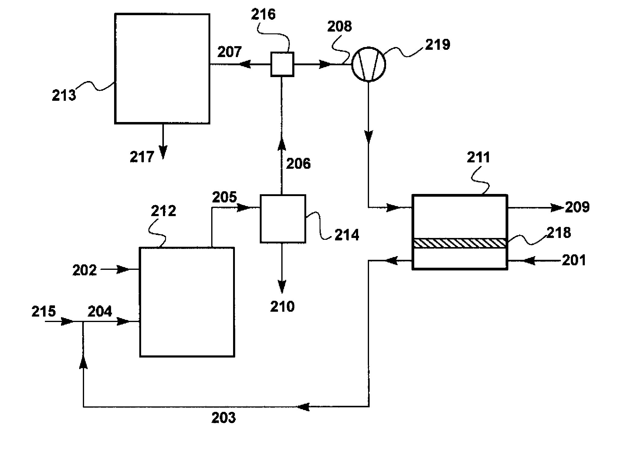
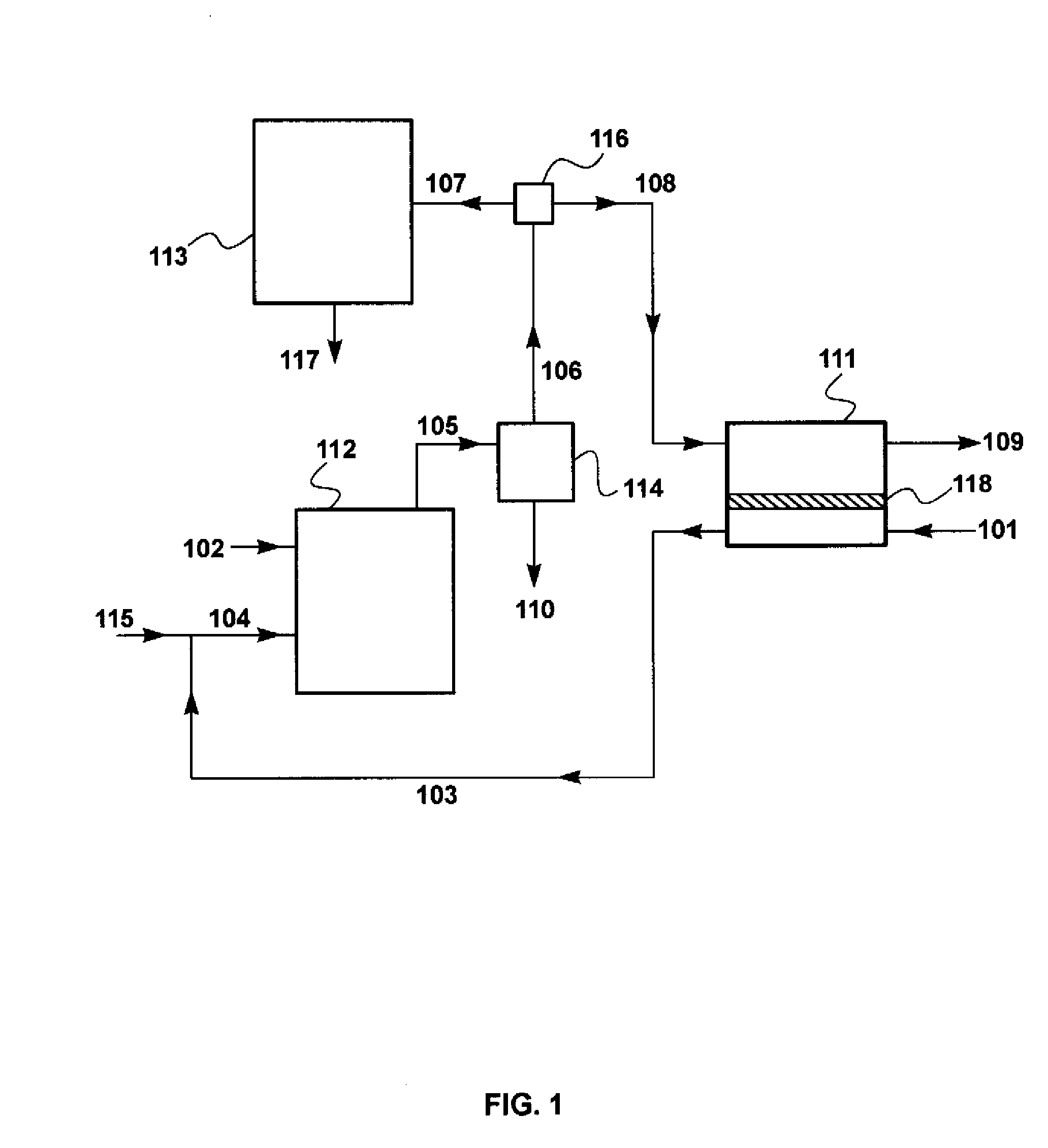
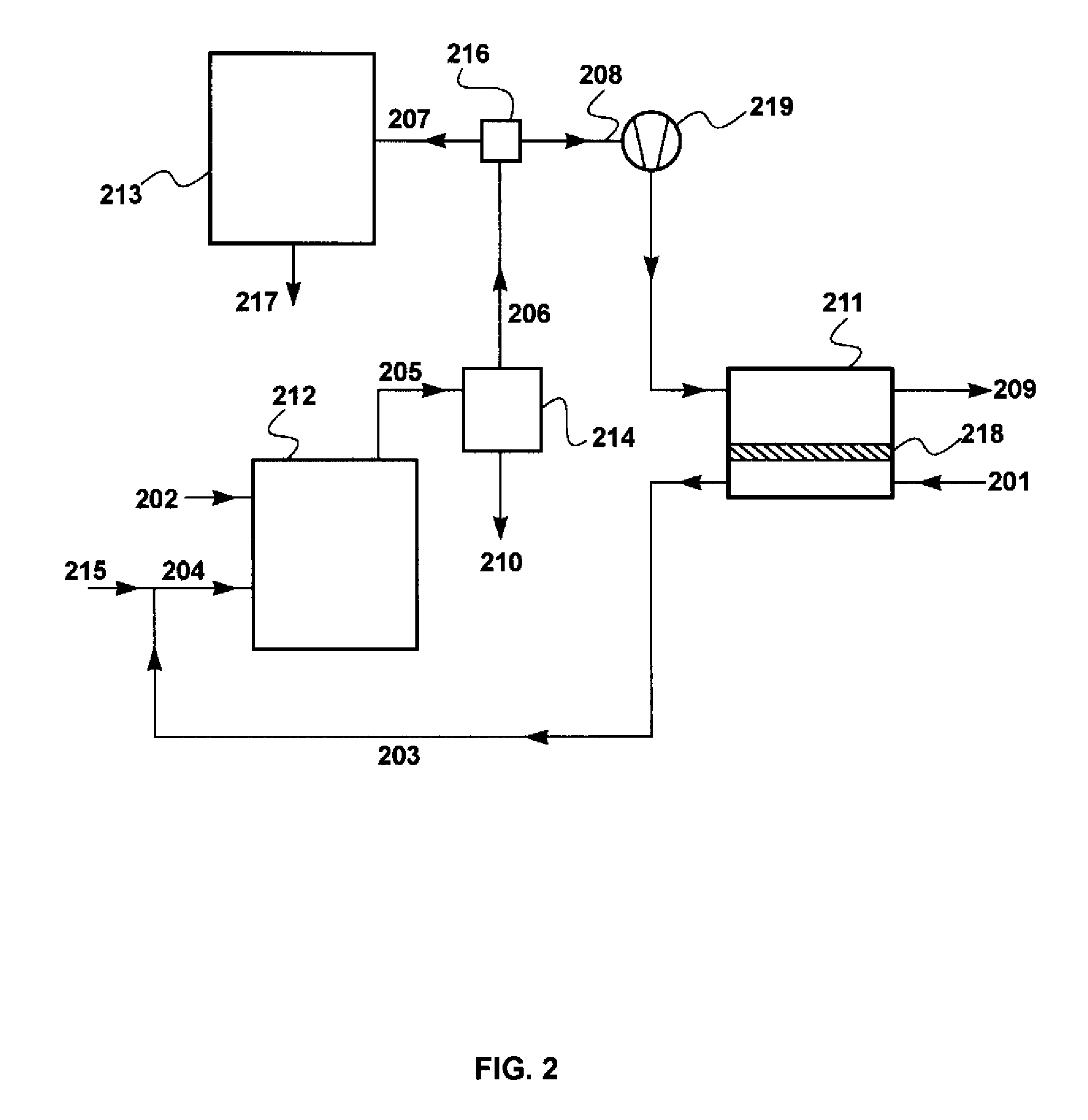
[0139]A set of calculations was performed to model the effect of various process parameters on the performance of the sweep-based membrane separation step and its effect on the combustion step. The calculations for Examples 2 through 8 were performed using the flow scheme shown in FIG. 1 and described in the Detailed Description, above. This flow scheme includes a sweep-based membrane separation step, 111.
[0140]To facilitate operation of the calculation software, the base case air flow provided to the combustor via the membrane permeate side was assumed to be about 740 m3 / h (950 kg / h), compared with the typical air flow to a 500 MW power plant of about 1.8 million m3 / h used for the calculation of Example 1. In other words, the scale of the calculations for Examples 2 through 8 was about 1 / 2,400 of the scale for a typical coal-fired power plant. This reduces membrane area proportionately, bu...
example 2
Embodiment of the Invention
[0141]In this example, the membrane area was assumed to be 400 m2, and the combustion exhaust stream split ratio was set at 1:1 (flow to carbon dioxide capture step:flow to sweep-based membrane separation step). The separation was assumed to be performed using a membrane having permeation properties as in Table 2. The results of this calculation are shown in Table 4.
TABLE 4Gas toCondenserCaptureMembraneAirGas toCoalKnockoutStepFeedSweepCombustorRetentateParameter / Stream(102)(110)(107)(108)(101)(103)(109)Total Flow (kg / h)55465545549501100404Temperature (° C.)25404040253325Pressure (bar)1.01.01.01.01.01.01.0Component (vol %)Coal (carbon +100000000hydrogen)Oxygen001.61.621.017.55.2Nitrogen0071.871.879.070.691.9Carbon Dioxide0019.219.208.32.9Water01007.47.403.60
[0142]Compared with the “no membrane” Example 1, the carbon dioxide content in the combustion exhaust stream 107 sent to the capture step is increased from 11.7 vol % to 19.2 vol %, and compared to Exam...
PUM
| Property | Measurement | Unit |
|---|---|---|
| vol % | aaaaa | aaaaa |
| pressure | aaaaa | aaaaa |
| area | aaaaa | aaaaa |
Abstract
Description
Claims
Application Information
 - R&D
- Intellectual Property
- Life Sciences
- Materials
- Tech Scout
- Unparalleled Data Quality
- Higher Quality Content
- 60% Fewer Hallucinations
Browse by: Latest US Patents, China's latest patents, Technical Efficacy Thesaurus, Application Domain, Technology Topic, Popular Technical Reports.
© 2025 PatSnap. All rights reserved.Legal|Privacy policy|Modern Slavery Act Transparency Statement|Sitemap|About US| Contact US: help@patsnap.com


