
Headphones with distortion-free loudness limiting and dynamic equalization device

a dynamic equalization and loudness limitation technology, applied in the field of headphone assembly, can solve the problems of less effective manual control, increased spl, and increased user spl, and achieve the effects of limiting the sound pressure level, reducing the rate of temperature drop, and small thermal mass

Active Publication Date: 2011-08-18
CHU WALTER KA WAI
View PDF2 Cites 17 Cited by
  • Summary
  • Abstract
  • Description
  • Claims
  • Application Information

AI Technical Summary

Benefits of technology

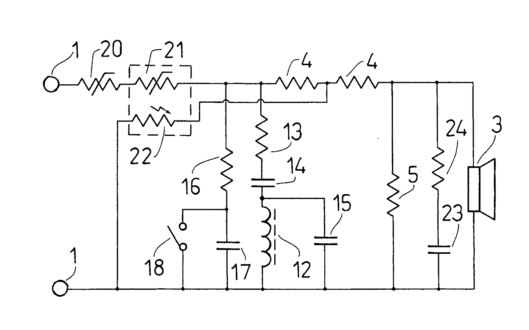
[0009]Another advantage of the present invention is to provide a voltage divider including a positive temperature coefficient resistor and a headphone driver, through which the sound pressure level delivered by the headphone driver is controllable in a precise manner.
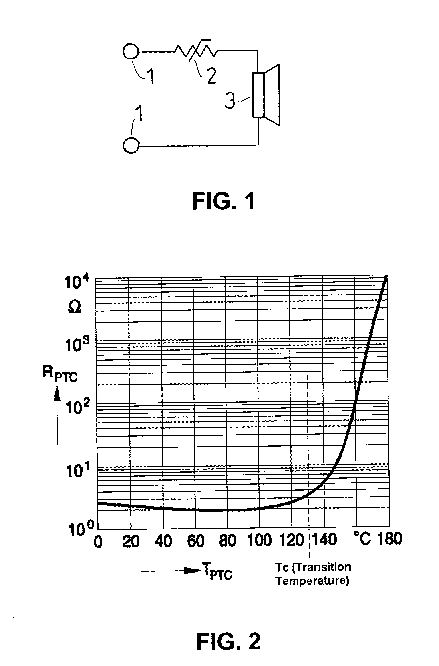
[0010]Another advantage of the present invention is to provide a positive temperature coefficient resistor operatively controlling the sound pressure level delivered by the headphone driver, wherein the resistance of the positive temperature coefficient resistor is increased in a non-linear manner with respect to the impedance of the headphone driver to limiting a power delivered to the headphone driver for automatically limiting a sound pressure level delivered by the headphone driver when the voltage is higher than a preset level.
[0011]Another advantage of the present invention is to provide a positive temperature coefficient resistor which has a small thermal mass such that the positive temperature coefficient resistor is promptly responsive to any input amplitude increasing and limiting the sound pressure level delivered by the headphone driver, thereby providing hearing protection and comfort.
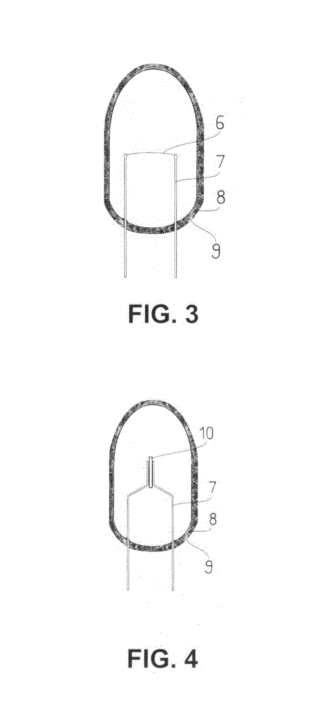
[0012]Another advantage of the present invention is to provide an encapsulation unit for defining an insulated environment for the positive temperature coefficient resistor such that the positive temperature coefficient resistor is sufficiently insulated from outside and the rate of temperature decrease is minimized, thereby allowing the proper functioning of the positive temperature coefficient resistor for providing hearing protection and perceiving the quality of the audio output.
[0013]Another advantage of the present invention is to provide a resonant notch filter which has a preset resonance frequency, preferably at 3.5 kHz, such that a resonant circuit effect is produced at the preset resonance frequency, thereby limiting the power delivered to the headphone driver at the notch frequency for automatically limiting the sound pressure level delivered by the headphone driver at the notch frequency.
[0014]Another advantage of the present invention is to provide a high frequency shunt circuit provided on the load side of the positive temperature coefficient resistor for providing a bass boosting response.

Problems solved by technology

An automatic means is preferred over manual control because manual adjustment of listening volume tends to be less effective because as users listen to audio material, their hearing adapts to the sound level, causing some users increase the SPL as the listening session proceeds.
Another reason manual control is less effective is because users sometimes cannot respond quickly enough to rapidly changing amplitudes of sound material to prevent hearing damage.
Active circuitry has the drawbacks of requiring a direct current power source and is often bulky.
Passive circuits known to date either simply reduce the efficiency of the headphones or clip the audio drive waveform, introducing severe distortion which makes their use unpleasing and also generates harmonics which results in low frequency power being shifted into higher frequencies where human hearing is more susceptible to damage, further reducing the effectiveness of simple clippers as automatic means of protecting hearing.

Method used


Image

  • Headphones with distortion-free loudness limiting and dynamic equalization device
  • Headphones with distortion-free loudness limiting and dynamic equalization device
  • Headphones with distortion-free loudness limiting and dynamic equalization device

Examples


Embodiment Construction

[0049]Referring to FIGS. 1 to 13, a headphone assembly according to a preferred embodiment of the present invention is illustrated.

[0050]For clarity, in this document, the figures illustrate one audio channel only. In stereo and other multiple channel audio systems there will be one instance of the circuit shown in the Figures for each audio channel.

[0051]Headphone refers an electrodynamic acoustic device for audio playback and is intend to placed near or inside the ear canals of a human. It can be one piece for one side of the ear only, but more commonly (as for music playback) a pair (stereo) for both ears. The term “headphones” in this document is used to describe circumaural (surrounding the ear) headphones, supra-aural (on the ear) headphones, earbuds (that seat in the concha), and canalphones (some people called it in-ear monitors).

[0052]FIG. 1 shows the minimal configuration of the basic invention according to a preferred embodiment of the present invention. Audio signals suc...


PUM


Abstract

A headphone assembly for generating an audio output with distortion-free loudness limiting and dynamic equalization feature includes a voltage divider comprising a positive temperature coefficient resistor and a headphone driver, and two audio signal input terminals in each audio channel connected to the voltage divider arranged for connecting to an audio device, wherein a large portion of the voltage of the audio signal to the two audio signal input terminals to appear across the headphone driver in response to the audio signal received through the two audio signal input terminals below a preset low amplitude level; and increasing a resistance of the positive temperature coefficient resistor in a preset non-linear manner and decreasing a voltage drop across the headphone driver accordingly in response to the audio signal received through the two audio signal input terminals which is higher than the preset low amplitude level.

Description

CROSS REFERENCE OF RELATED APPLICATION[0001]This is a non-provisional application that claims the benefit of priority under 35U.S.C.§119 to a provisional application, application No. 61 / 305,553, filed Feb. 18, 2010.BACKGROUND OF THE PRESENT INVENTION[0002]1. Field of Invention[0003]The present invention relates to a headphone assembly, and more particularly to headphones with distortion-free loudness limiting and dynamic equalization feature.[0004]2. Description of Related Arts[0005]In many applications of headphones, some automatic method of limiting the SPL (Sound Pressure Level) at the opening of the user's ear canals is highly desirable for the purposes of both comfort and hearing conservation. An automatic means is preferred over manual control because manual adjustment of listening volume tends to be less effective because as users listen to audio material, their hearing adapts to the sound level, causing some users increase the SPL as the listening session proceeds. Another r...

Claims


Application Information

Patent Timeline
Patent Type & Authority Applications(United States)
IPC IPC(8): H04R1/10
CPCH04R3/007H04R1/10
Inventor CHU, WALTER KA WAI
Owner CHU WALTER KA WAI
Learn More