
Systems and Methods for Optically Generated Trigger Multiplication

a multiplication system and optical generation technology, applied in the field of interferometry, can solve the problems of only providing a single sampling trigger and a sinusoidal reference signal, and present practical difficulties

Active Publication Date: 2011-08-18
BAKER HUGHES INC
View PDF8 Cites 3 Cited by
  • Summary
  • Abstract
  • Description
  • Claims
  • Application Information

AI Technical Summary

Benefits of technology

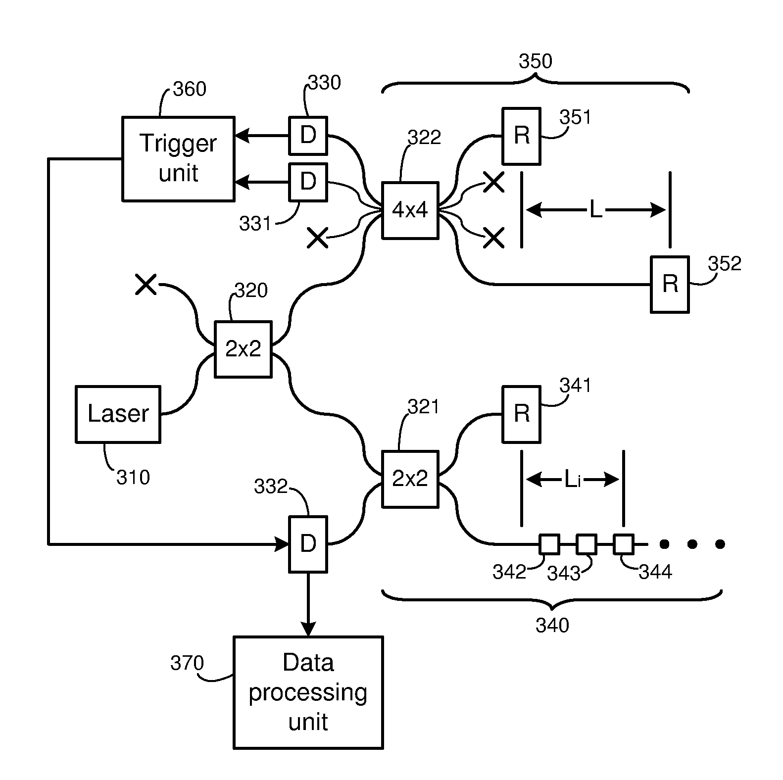
[0007]This disclosure is directed to systems and methods for providing trigger signals in an optical interrogator that solve one or more of the problems discussed above. In particular, the systems and methods provide for the generation of multiple triggers within each period of a varying reference signal, where the triggers are substantially evenly spaced according to the wavenumber of the reference signal.

Problems solved by technology

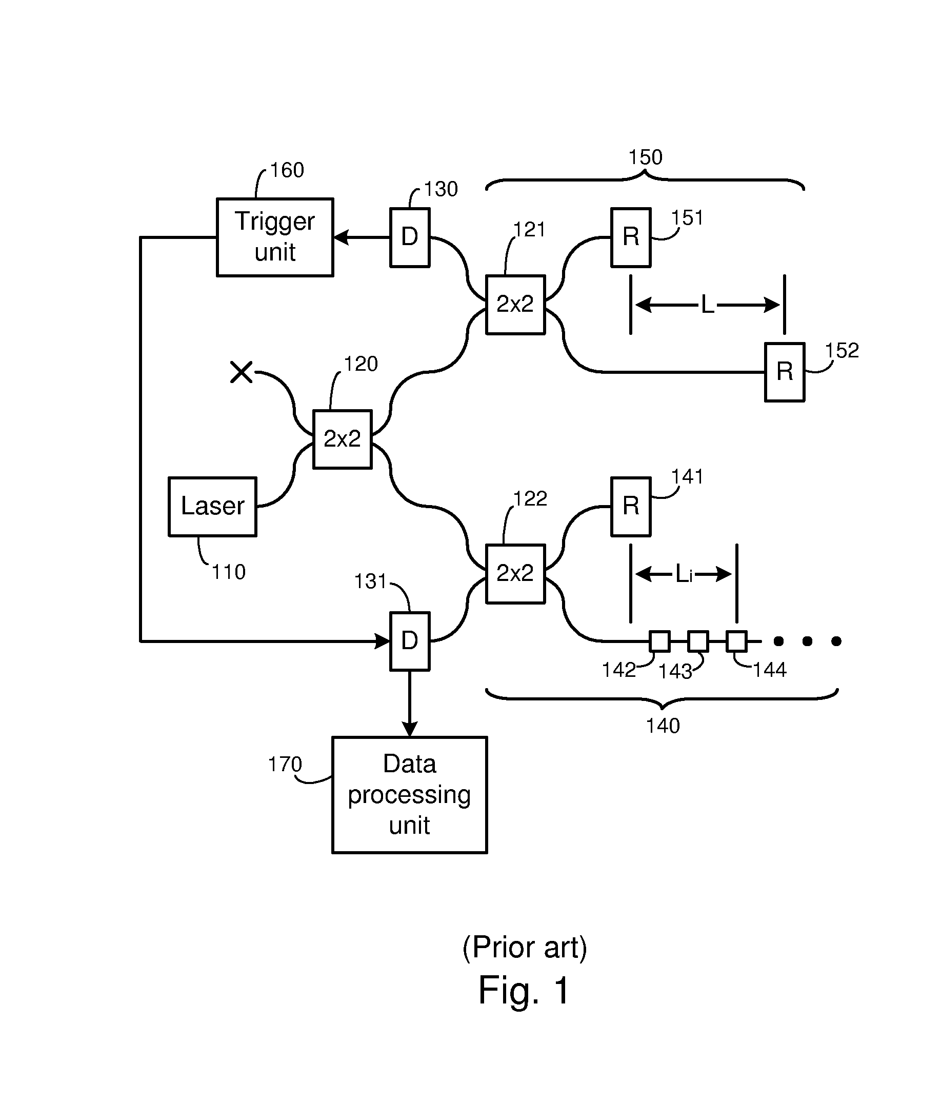
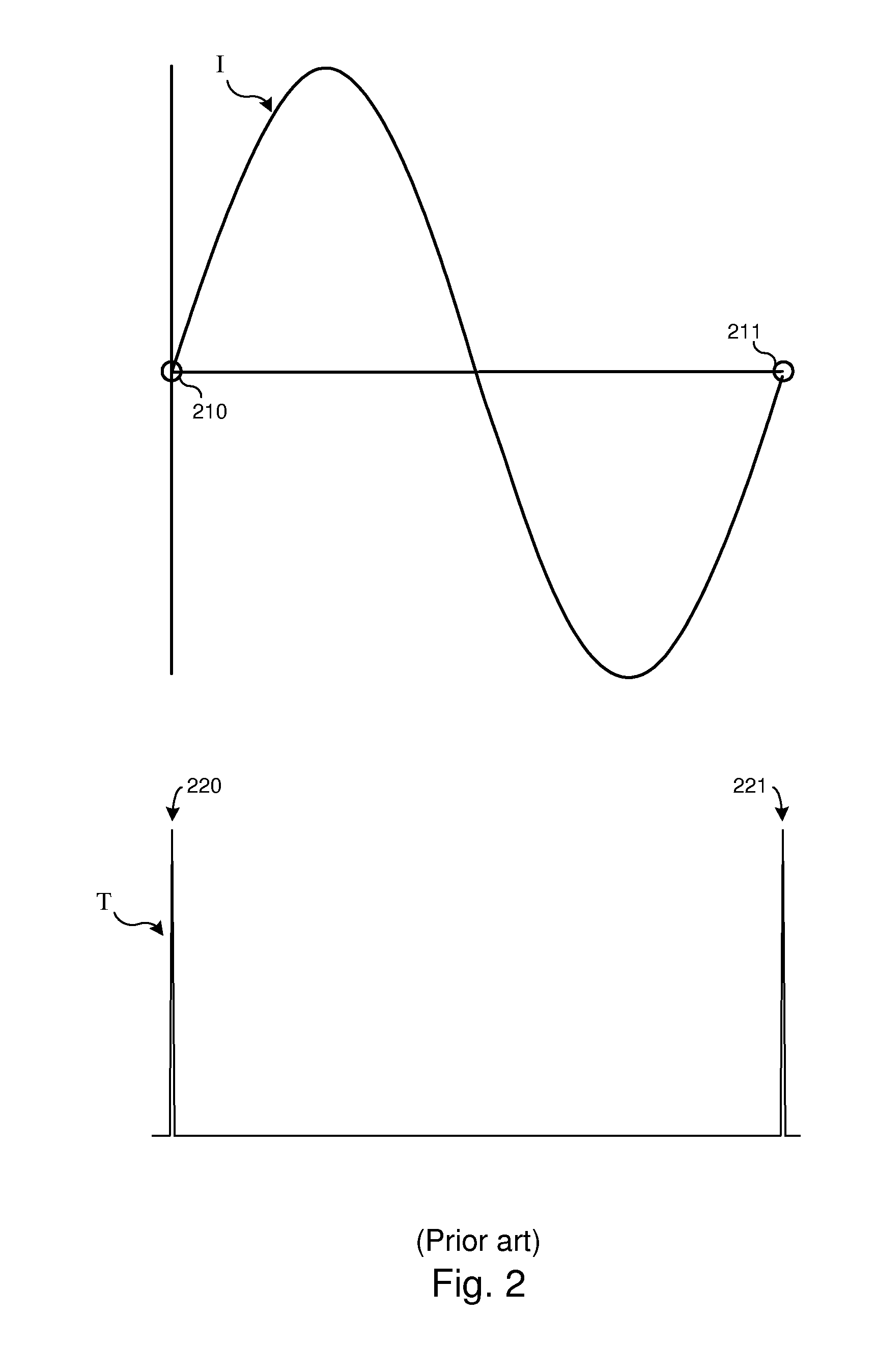
One of the problems with conventional OFDR systems of the type described above is that the sinusoidal reference signal provides sampling triggers only once per period, for instance at rising zero-crossings.
This may present practical difficulties, however.

Method used


Image

  • Systems and Methods for Optically Generated Trigger Multiplication
  • Systems and Methods for Optically Generated Trigger Multiplication
  • Systems and Methods for Optically Generated Trigger Multiplication

Examples


Embodiment Construction

[0020]One or more embodiments of the invention are described below. It should be noted that these and any other embodiments described below are exemplary and are intended to be illustrative of the invention rather than limiting.

[0021]As described herein, various embodiments of the invention comprise systems and methods for providing trigger signals in an optical interrogator, wherein multiple triggers are generated within each period of a varying reference signal, and wherein the triggers are evenly spaced according to the wavenumber of the reference signal.

[0022]In one embodiment, an OFDR system is used to interrogate a sensor array that is embedded in an optical fiber. A laser provides a beam to both the sensor array and a reference interferometer. The reference interferometer produces a reference signal that is passed through a 4×4 optical coupler which splits the signal and provides output signals that are 90 degrees out of phase with each other. Optical detectors are used to co...


PUM


Abstract

Systems and methods for providing trigger signals in an optical interrogator, wherein multiple triggers are generated within each period of a varying reference signal, and wherein the triggers are evenly spaced according to the wavenumber of the reference signal. In one embodiment, an optical frequency domain reflectometry system provides a laser beam to a reference interferometer to produce a reference signal. This signal is passed through a 4×4 optical coupler which splits the signal into a first signal and a second signal that is 90 degrees out of phase with the first signal. These signals are converted to electrical signals, and a trigger unit generates triggers at points at which the two electrical signals have zero-crossings, and at which the magnitudes of the signals are equal. The resulting triggers remain evenly spaced within the period of the reference signals, even when the period is changed.

Description

BACKGROUND [0001]1. Field of the Invention[0002]The invention relates generally to interferometry and more particularly to systems and methods for generating multiple triggers for each cycle of a sampling signal in an optical interrogator.[0003]2. Related Art[0004]The commercial success of optical fiber telecommunications has fostered the growth of optical fiber sensing applications by providing a ready supply of low cost, high quality components and test equipment. Another enabling technology for fiber sensing was the discovery of the ultraviolet (UV) photosensitivity in optical fiber. Photosensitivity allows the alteration of the internal structure of a fiber waveguide. Modification of the waveguide can be employed for a number of useful purposes, one of which is to induce a periodic modulation of the refractive index along the fiber core to create a wavelength selective reflector called a fiber Bragg grating (FBG). FBG's can be produced conveniently and very inexpensively during ...

Claims


Application Information

Patent Timeline
Patent Type & Authority Applications(United States)
IPC IPC(8): G01B9/02
CPCG01B11/18G01B9/02G01B9/02069G01B2290/60G01B11/165H04B10/071
Inventor CHILDERS, BROOKS A.DUNCAN, ROGER G.
Owner BAKER HUGHES INC
Learn More