
Optical coherence tomographic imaging apparatus

a tomographic imaging and optical coherence technology, applied in the field of optical coherence tomographic imaging apparatus, can solve the problems of reducing the accuracy of spectral information and the upper limit of tomographic spectral information, and achieve the effect of high wavelength accuracy

Inactive Publication Date: 2011-08-18
CANON KK
View PDF9 Cites 10 Cited by
  • Summary
  • Abstract
  • Description
  • Claims
  • Application Information

AI Technical Summary

Benefits of technology

[0034]The present invention realizes an optical coherence tomographic imaging apparatus capable of outputting tomographic spectral information corresponding to an optical coherence tomographic image with high wavelength accuracy.

Problems solved by technology

However, the OCT device described above has a problem in that if the accuracy of position is increased when obtaining tomographic spectral information at a certain position in a tomographic image, the accuracy of the spectral information will be decreased.
However, it is known from a restriction in principle based on the Fourier transformation that a product of the resolution δz in a depth direction and the accuracy δν of the tomographic spectral information have an upper limit.

Method used


Image

  • Optical coherence tomographic imaging apparatus
  • Optical coherence tomographic imaging apparatus
  • Optical coherence tomographic imaging apparatus

Examples


first embodiment

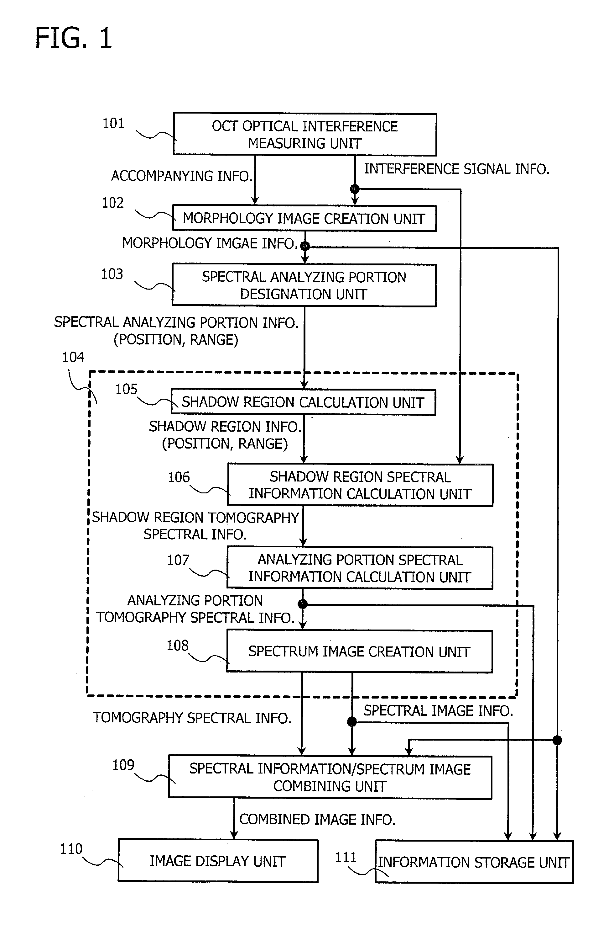
[0066]FIG. 1 is a function block diagram schematically showing an optical coherence tomographic imaging apparatus according to an embodiment of the present invention.

[0067]The optical coherence tomographic imaging apparatus has an OCT optical coherence measuring unit 101 for measuring an optical interference signal and a morphology image creation unit 102 for creating an optical coherence tomographic image based on the information.

[0068]The OCT optical interference measuring unit 101 obtains, creates, and outputs optical interference signal information and its accompanying information, i.e. position information (a tomography depth direction and a direction orthogonal to the tomography depth direction). That is, the OCT optical interference measuring unit 101 branches illumination light outgoing from a light source to reference light and signal light and obtains the optical interference signal information by combining the reference light and the signal light which is incident in an i...

second embodiment

[0119]A second embodiment of the present invention will be described below with reference to FIGS. 11A, 11B, and 12A to 12C.

[0120]The second embodiment shows an example in which the standardization of the optical spectrum, which is performed by the standardization means of the first embodiment, is modified in order to more increase the accuracy of the optical spectrum in a spectral analyzing portion.

[0121]In the second embodiment, when the spectral information processing unit 104 discriminates the shadow region 502 as a deeper region, it further sets an extended region 1101 as shown in FIGS. 11A and 11B. The extended region 1101 is a sum of the shadow region 502 and the spectral analyzing portion 501. In a spectral information calculation as a next step, after a square processing is separately performed by multiplying a window function corresponding to the extended region 1101 to an interference signal in addition to a window function to the shadow region 502, the Fourier transforma...


PUM


Abstract

An optical coherence tomographic imaging apparatus for splitting light emitted from a light source into reference light and signal light and creating an optical coherence tomographic image and tomographic spectral information in a predetermined spectral analyzing portion in the optical coherence tomographic image based on optical interference signal information of the reference light and the signal light which are incident on an inspection target and reflected on respective layers, the optical coherence tomographic imaging apparatus including a spectral information processing unit for performing a spectral information calculation using an optical interference signal of a deeper region and creating the tomographic spectral information of the spectral analyzing portion. With this arrangement, spectral information corresponding to the optical coherence tomographic image can be output with high wavelength accuracy.

Description

TECHNICAL FIELD[0001]The present invention relates to an optical coherence tomographic imaging apparatus applied to a disease diagnosis apparatus and the like using, for example, a fundus / retinal image, and more particularly to an optical coherence tomographic imaging apparatus for creating tomographic spectral information together with an optical coherence tomographic image by optical interference signal information.BACKGROUND ART[0002]Recently, an optical coherence tomographic imaging apparatus making use of a technique of a low-coherence interferometer or a white light interferometer has come into practical use. The device, which is often called OCT (Optical Coherence Tomography) device, is used particularly in an ophthalmologic field to obtain a fundus tomographic image. Further, the device also tries to perform a tomographic observation of a skin and tomographic imaging of digestive and circulatory organ walls by being arranged as an endoscope and a catheter in addition to the ...

Claims


Application Information

Patent Timeline
Patent Type & Authority Applications(United States)
IPC IPC(8): G01J3/45
CPCA61B3/102G01N21/4795G01N2021/1787G01B2290/45G01B9/02074G01B9/02089G01B9/02091
Inventor SUGITA, MITSURO
Owner CANON KK
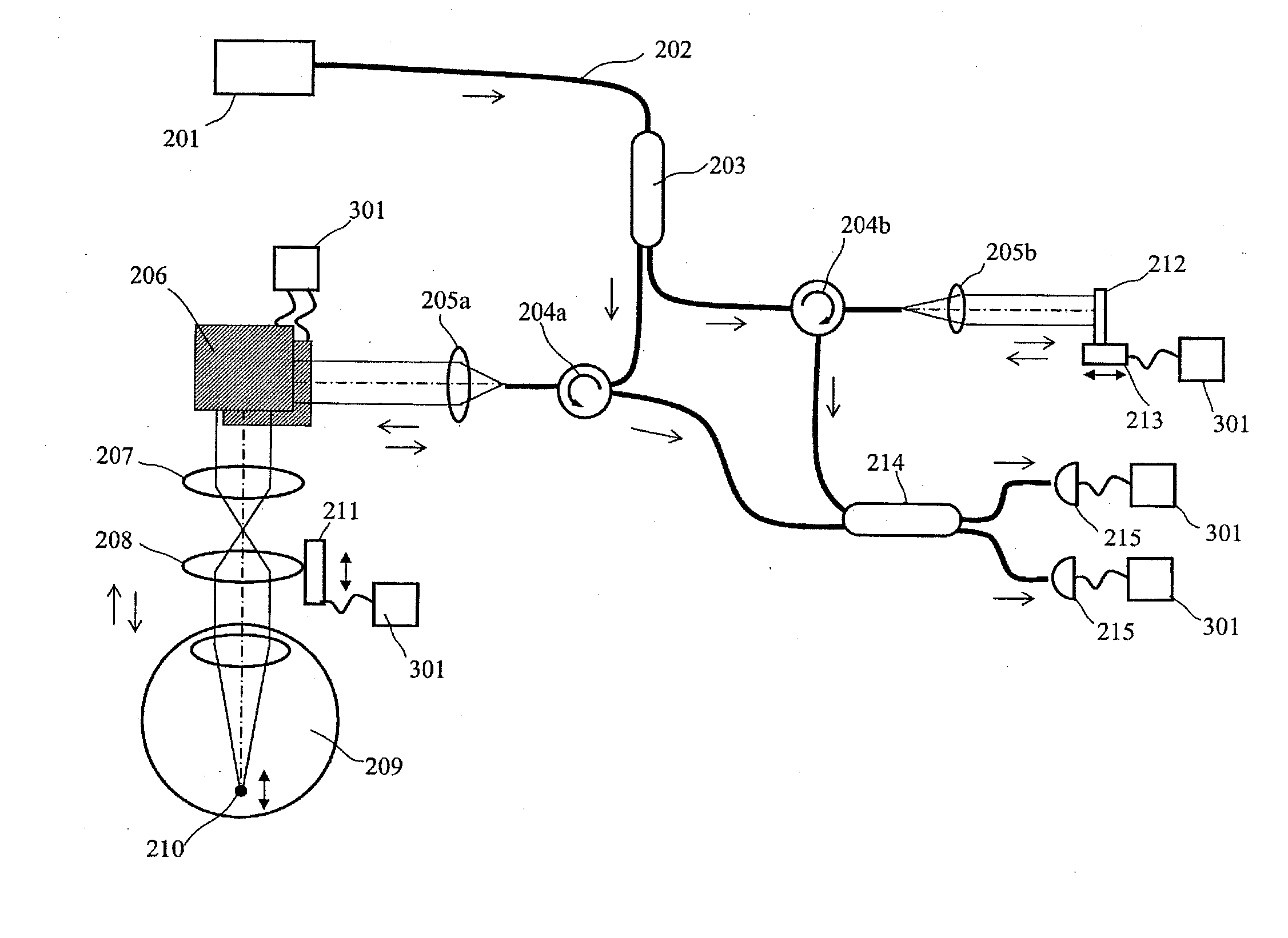
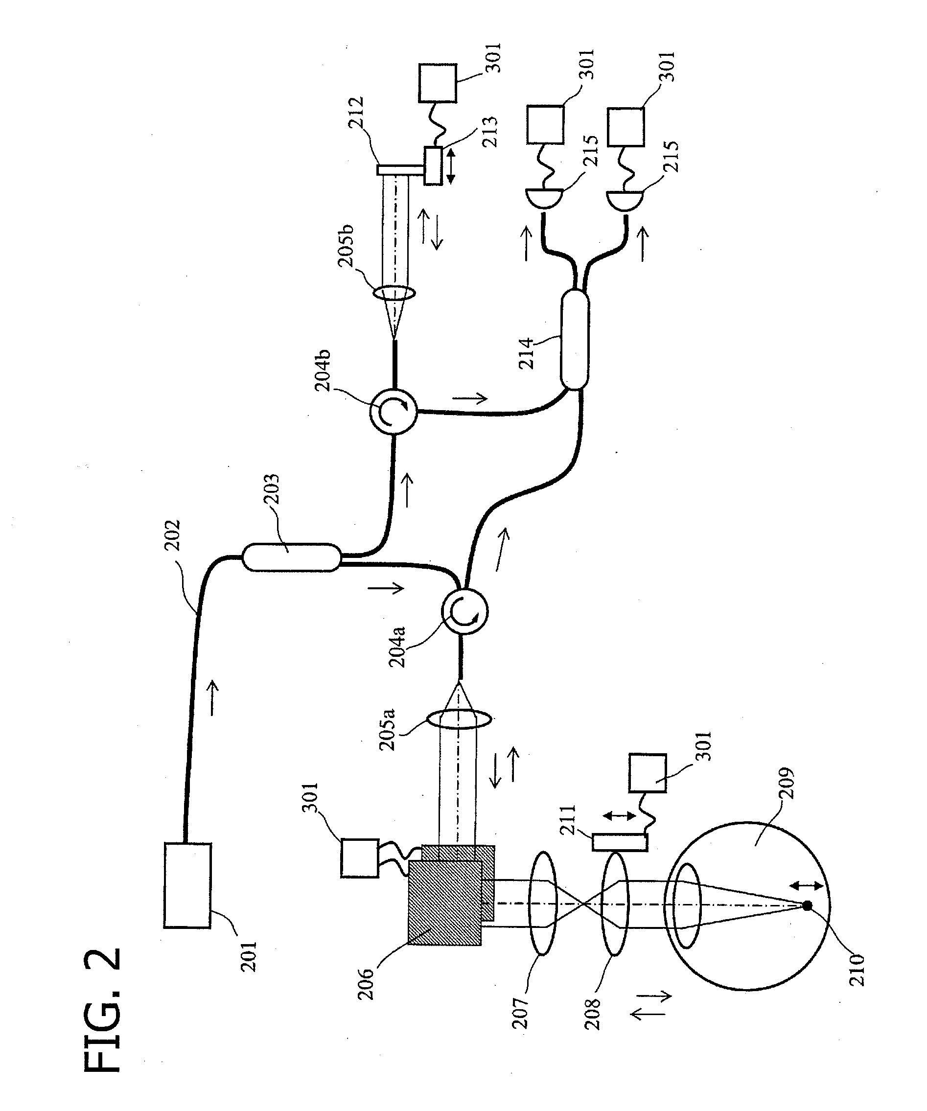
Learn More