Eureka AIR delivers breakthrough ideas for toughest innovation challenges, trusted by R&D personnel around the world.

Method and apparatus for optical spectrum analysis

a spectrum analysis and optical spectrum technology, applied in the field of optical spectrum analysis, can solve the problems of rapid worsening of the accuracy of the osa results, and achieve the effect of enhancing the accuracy of the average wavelength average and higher wavelength resolution of such functions

Inactive Publication Date: 2010-06-10
AGILENT TECH INC
View PDF3 Cites 0 Cited by
  • Summary
  • Abstract
  • Description
  • Claims
  • Application Information

AI Technical Summary

Benefits of technology

[0009] It is therefore an advantage of such embodiments that the accuracy of the finally determined wavelength is about significant higher than of a prior art OSA, i.e., the wavelength accuracy of embodiments of the present invention can be as high as 1-2 pm.
[0011] Since wavelength detection units can be calibrated with a higher accuracy than known OSAs, embodiments of the present invention enable the afore mentioned strong enhancement of the possible wavelength accuracy down to 1-2 pm.
[0015] The transfer function T(λ) is preferably linear or nearly linear to enhance the accuracy of the average wavelength λaverage.
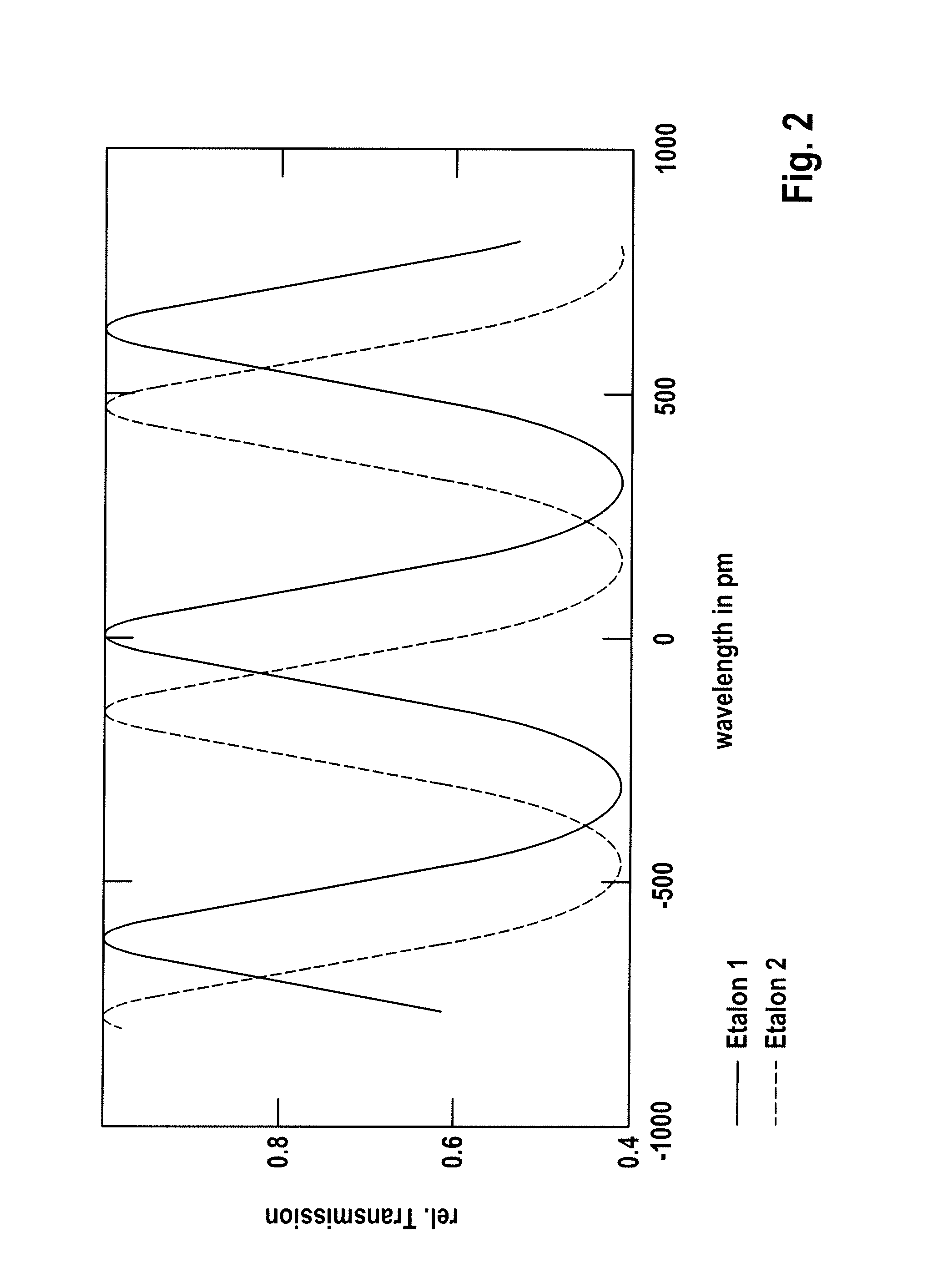
[0016] In a preferred embodiment of the present invention the transfer function T(λ) is realized by using at least two cyclical or periodic functions which are phase shifted with respect to each other. Using such periodic functions is advantageous with respect to a simple linear filter because the wavelength resolution of such functions is higher. However, the use of a simple linear filter is also possible.

Problems solved by technology

Furthermore, since the calibration result of the OSA is dependent on ambience parameters, e.g. the temperature in the ambience of the OSA, the accuracy of the OSA results are worsening rapidly with time because of a change of such parameters with time.

Method used


Image

  • Method and apparatus for optical spectrum analysis
  • Method and apparatus for optical spectrum analysis
  • Method and apparatus for optical spectrum analysis

Examples


Embodiment Construction

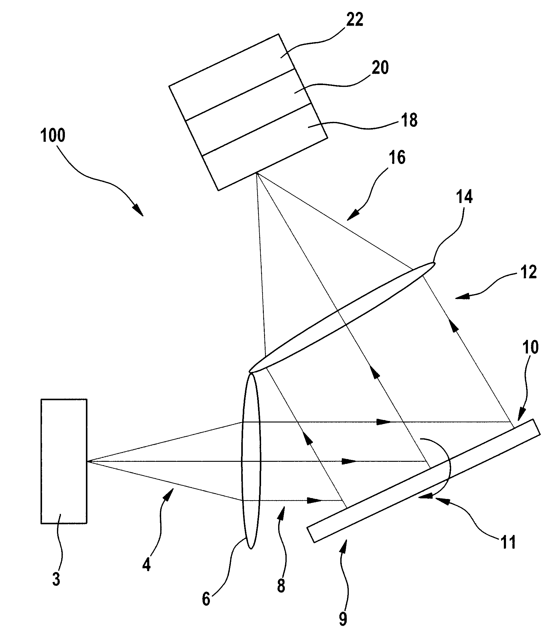
[0030] Referring now in greater detail to the drawings, FIG. 1 shows a schematic illustration of an apparatus 100 for optical spectrum analysis of an optical spectrum of a light beam 4 according to a preferred embodiment of the present invention. Apparatus 100 generally can be defined as an OSA since apparatus 100 functions as a known OSA but has the additional inventive features described below. Therefore, for simplification purposes, the drawings and the following description of the drawings do not describe in detail generally known features of an OSA. However, such known features are forming a part of apparatus 100 of FIG. 1, If necessary. Such known features of an OSA are for example disclosed in U.S. Pat. No. 5,233,405, the disclosure of which is fully incorporated herein by reference.

[0031] An unknown light beam 4 under measurement is coming from a source 3. The light beam 4 under measurement is provided to a lens 6 to collimate the original light beam 4 into a collimated lig...


PUM


Abstract

The present invention relates to an apparatus and to a method of optical spectrum analysis of an optical spectrum of a light beam (4), comprising the steps of selecting a certain part of the optical spectrum of the light beam (4) to provide a filtered light beam (12), detecting the filtered light beam (12) to provide an electrical signal corresponding to a power amplitude (O(λ)) of the filtered light beam (12), detecting the filtered light beam (12) to provide an electrical signal corresponding to a wavelength of the filtered light beam (12), and providing the power amplitude as a function of the wavelength of the filtered light beam (12).

Description

BACKGROUND OF THE INVENTION [0001] The present invention relates to optical spectrum analysis of an optical signal. [0002] Optical spectrum analysis serves to analyze an unknown spectrum to determine the power of certain wavelengths of the spectrum. For such an analysis it is normally used an optical spectrum analyzer (OSA) which typically comprises a pivotable grating. The grating serves to disperse the light under measurement and so to select a certain wavelength of the spectrum. By pivoting the grating the spectrum can be analyzed. To allocate a certain wavelength to a certain pivot angle it is necessary to calibrate the OSA in advance. For such a calibration sharp laser lines, gas absorption lines or reflection lines of fiber Bragg gratings or Fabry-Perot filters with a known wavelength are usually used. [0003] The resolution bandwidth (RBW) of such an OSA is substantially given by the formula RBW=λ / (n N), with λ being the wavelength, N being the number of grating passes, and n ...

Claims


Application Information

Patent Timeline
Patent Type & Authority Applications(United States)
IPC IPC(8): G01J3/28
CPCG01J3/02G01J9/00G01J3/1804G01J3/027
Inventor MAESTLE, RUEDIGER
Owner AGILENT TECH INC
Why Eureka
Eureka Blog
Learn More