
Optical touch device

a touch screen and optical technology, applied in the field of optical touch devices, can solve the problems of increasing reducing the current consumption of electronic devices in power-saving mode, and reducing the current consumption of optical touch screens

Inactive Publication Date: 2011-08-18
PIXART IMAGING INC
View PDF26 Cites 19 Cited by
  • Summary
  • Abstract
  • Description
  • Claims
  • Application Information

AI Technical Summary

Benefits of technology

The present invention is an optical touch device that solves the problem of high current consumption when detecting a wakeup time. The device comprises more than one image sensor and a processing unit. When the device is in a sleep mode, one of the image sensors is enabled to detect an indication object on a touch area. When the image sensor detects the indication object, it notifies the processing unit to wake up the entire device. The enabled image sensor may detect the indication object with a lower frequency when in sleep mode to reduce current consumption. The device may also include a timer to periodically actuate the image sensors and a light-emitting element to determine the wakeup time of the device. The invention meets the specification of 2.5 mA current consumption.

Problems solved by technology

Moreover, requirements on current consumption of the electronic devices in a power-saving mode become stricter.
However, when detecting on a wakeup time, the optical touch screen produces a high current consumption, and thus the specification of 2.5 mA current consumption cannot be met.

Method used


Image

  • Optical touch device
  • Optical touch device
  • Optical touch device

Examples


Embodiment Construction

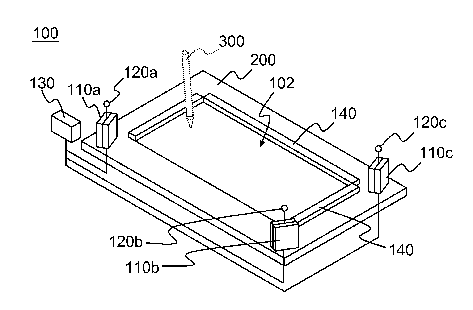
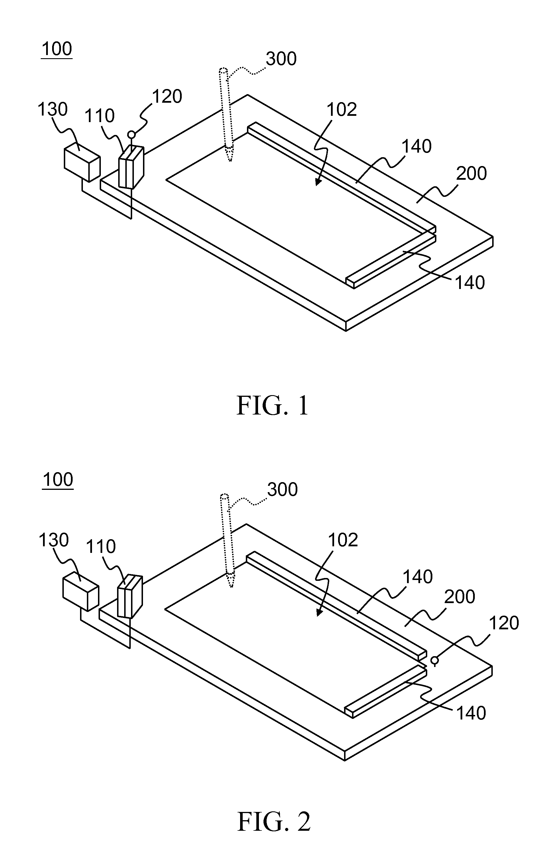
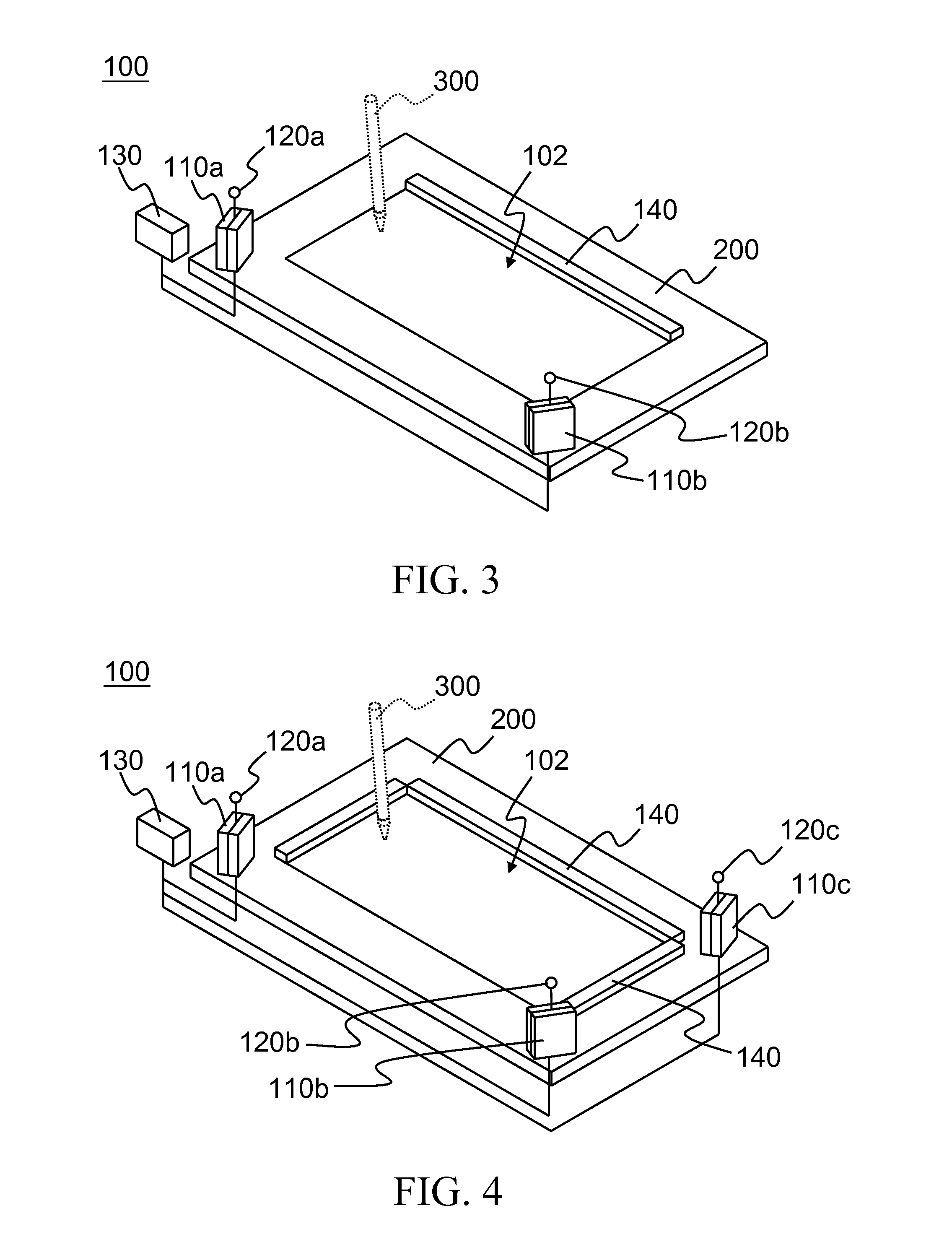
[0037]Referring to FIGS. 1, 2, 3 and 4, an optical touch device 100 may be located on a display screen 200 (such as an LCD screen, a cathode-ray tube display screen, and an electronic whiteboard).

[0038]The optical touch device 100 is used for providing a touch area 102. Moreover, an image sensor 110 and a light-emitting element 120 are disposed in a corner of the touch area 102. The image sensor 110 is electrically connected to a processing unit 130. The processing unit 130 is used for controlling the operation of the optical touch device 100.

[0039]A single image sensor 110 may be disposed in one optical touch device 100 (as shown in FIGS. 1 and 2), or more than two image sensors 110a, 110b, and 110c (all referred to as 110) may also be disposed (as shown in FIGS. 4 and 5). A single light-emitting element 120 may be disposed in one optical touch device 100 (as shown in FIGS. 2 and 3), or more than two light-emitting elements 120a, 120b, and 120c (all referred to as 120) may also be ...


PUM


Abstract

An optical touch device is presented. When the optical touch device is in a sleep mode, only one of all image sensors of the optical touch device is enabled to detect an indication object on a touch area, so as to determine a wakeup time of the entire optical touch device.

Description

CROSS-REFERENCE TO RELATED APPLICATIONS[0001]This non-provisional application claims priority under 35 U.S.C. §119(a) on Patent Application No(s). 099203298 filed in Taiwan, R.O.C. on Feb. 12, 2010, the entire contents of which are hereby incorporated by reference.BACKGROUND OF THE INVENTION[0002]1. Field of Invention[0003]The present invention relates to a mechanism for waking up an electronic device from a sleep mode, and more particularly to an optical touch device.[0004]2. Related Art[0005]As more and more attentions are paid to green energy, a power-saving design has been considered necessary for electronic devices. Moreover, requirements on current consumption of the electronic devices in a power-saving mode become stricter.[0006]A sleep mode is a power-saving mode of the electronic devices. While an electronic device is in the sleep mode, when a user wants to use the electronic device again, the electronic device may continue to work in full power very quickly (usually in a f...

Claims


Application Information

Patent Timeline
Patent Type & Authority Applications(United States)
IPC IPC(8): G06F3/042
CPCG06F1/3262G06F3/0421G06F3/0416
Inventor KAO, MING TSANYANG, WEN YU
Owner PIXART IMAGING INC
Learn More