Heat exhaustion structure for heat dissipating device

a heat dissipating device and heat exhaustion technology, which is applied in the direction of electrical apparatus casings/cabinets/drawers, semiconductor/solid-state device details, instruments, etc., can solve the problems of reducing tolerance, forming gaps, and difficult to apply the scheme to an electronic device, so as to effectively exhaust the heat generated within the electronic device and prevent the heat from being transferred

Inactive Publication Date: 2011-08-18
ELECTRONICS & TELECOMM RES INST
View PDF18 Cites 6 Cited by
  • Summary
  • Abstract
  • Description
  • Claims
  • Application Information

AI Technical Summary

Benefits of technology

According to embodiments of the present invention, a heat generated by a heat dissipating device may be transferred to a heat sink or a case by concentrating or reflecting the heat, and thus it is possible to effectively exhaust a heat generated within an electronic device.
Additionally, according to embodiments of the present invention, when substrates are piled up, it is possible to prevent a heat from being transferred from a lower substrate to an upper substrate or other substrates.

Problems solved by technology

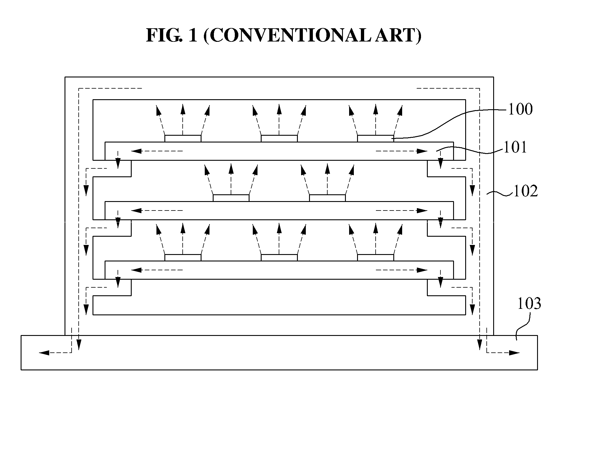
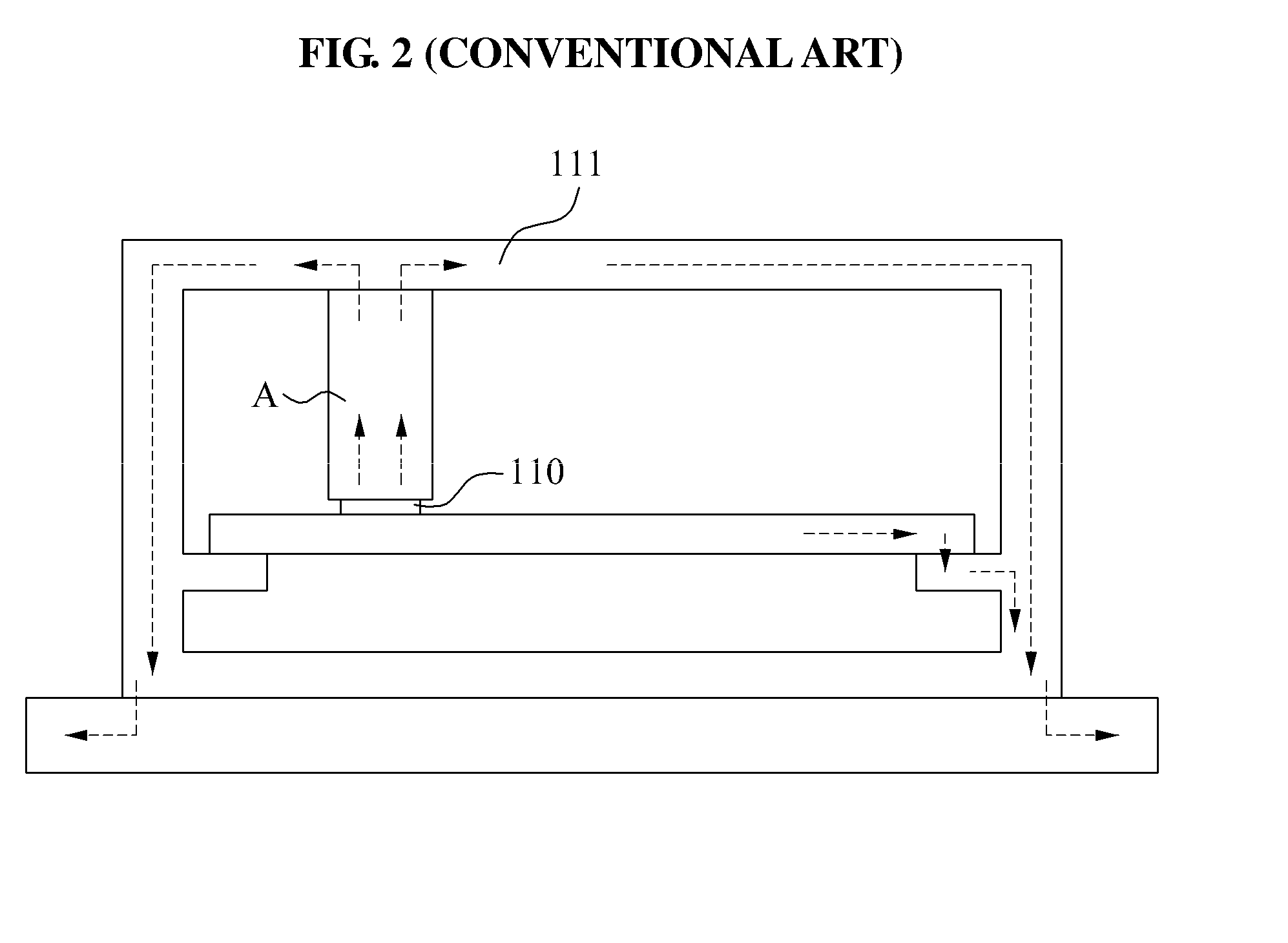
However, it is difficult to apply the scheme to an electronic device, such as a high-frequency high-power amplifier, of which the environment and the side of the PC need to be separated completely.
Additionally, in both the examples, processing may be performed so that a manufacturing tolerance may be reduced, however, problems occur that a gap may be formed due to an actual size by an assembling tolerance.

Method used


Image

  • Heat exhaustion structure for heat dissipating device
  • Heat exhaustion structure for heat dissipating device
  • Heat exhaustion structure for heat dissipating device

Examples


Embodiment Construction

Reference will now be made in detail to exemplary embodiments of the present invention, examples of which are illustrated in the accompanying drawings, wherein like reference numerals refer to the like elements throughout. Exemplary embodiments are described below to explain the present invention by referring to the figures.

FIG. 3 is a diagram illustrating a heat exhaustion structure for a heat dissipating device according to an embodiment of the present invention.

Referring to FIG. 3, the heat exhaustion structure may include a heat dissipating device 300, a Printed Circuit Board (substrate) 310, a case 320, and an infrared lens 330.

The heat dissipating device 300 may be installed on a side of the substrate 310, and may be implemented as various types of electronic devices and components, for example, a condenser, a semiconductor device, a sensor, a transistor, an amplifier, a diode, and the like.

The substrate 310 where the heat dissipating device 300 is installed may provide a conn...


PUM


Abstract

A heat exhaustion structure for a heat dissipating device is provided. The present invention relates to a heat exhaustion structure for a heat dissipating device, and more particularly, to a heat exhaustion structure that may effectively exhaust an internal heat generated by heat dissipating devices included in a semiconductor package and in a large number of electronic products.

Description

CROSS-REFERENCE TO RELATED APPLICATIONSThis application claims the benefit of Korean Patent Application No. 10-2010-0013297 and of Korean Patent Application No. 10-2010-0088728, respectively filed on Feb. 12, 2010 and Sep. 10, 2010, in the Korean Intellectual Property Office, the disclosures of which are incorporated herein by reference.BACKGROUND1. Field of the InventionThe present invention relates to a heat exhaustion structure for a heat dissipating device, and more particularly, to a heat exhaustion structure that may effectively exhaust an internal heat generated by heat dissipating devices included in a semiconductor package and in a large number of electronic products.2. Description of the Related ArtGenerally, a heat generated in an electronic device is exhausted to the outside, by using forced or natural convection and using conduction. In particular, in an example in which a inlet port and an exhaust port are included in an electronic device, a scheme of drawing in an ext...

Claims


Application Information

Patent Timeline
Patent Type & Authority Applications(United States)
IPC IPC(8): F28D15/04F28F7/00
CPCF28D15/02H01L23/34H01L23/427H05K7/20436H01L2924/0002H01L2924/00
Inventor KWAK, CHANG SOO
Owner ELECTRONICS & TELECOMM RES INST
Why Eureka
Try Eureka