Vehicle display system and motor control device therefor
a technology of display system and control device, which is applied in the direction of motor/generator/converter stopper, dynamo-electric converter control, instruments, etc., can solve the problems of the temporary displacement of the display position of the imag
- Summary
- Abstract
- Description
- Claims
- Application Information
AI Technical Summary
Benefits of technology
Problems solved by technology
Method used
Image
Examples
first embodiment
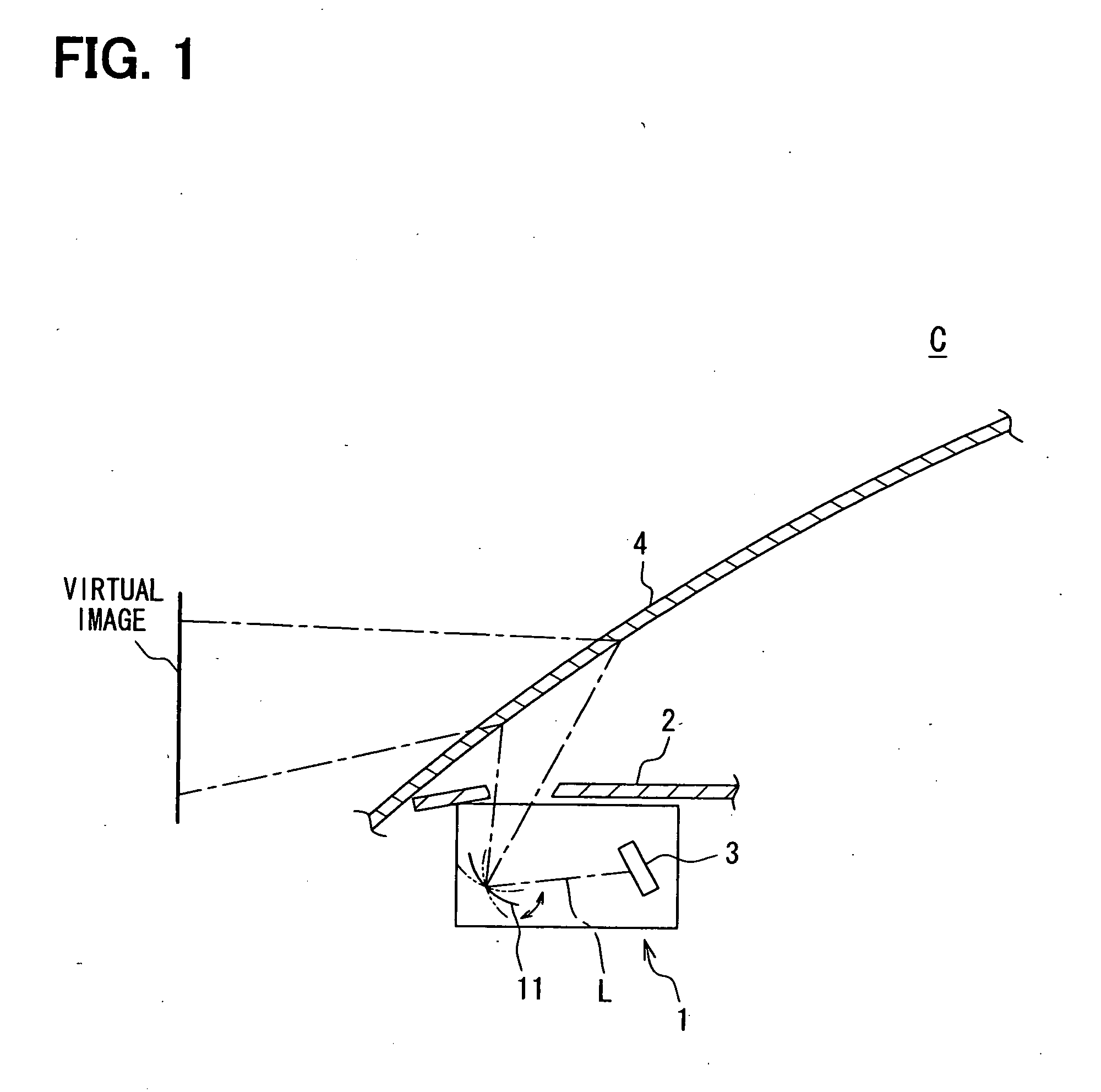
[0036]A vehicle display system and a motor control device therefor according to a first embodiment of the present invention will be explained with reference to FIGS. 1 to 4. A display system 1 of the first embodiment is a so-called vehicle HUD system, according to which an image displayed by a display device 3 is reflected by a mirror 11 and the image is displayed on a windshield 4 of a vehicle. At first, an entire system including the display system 1 will be explained.
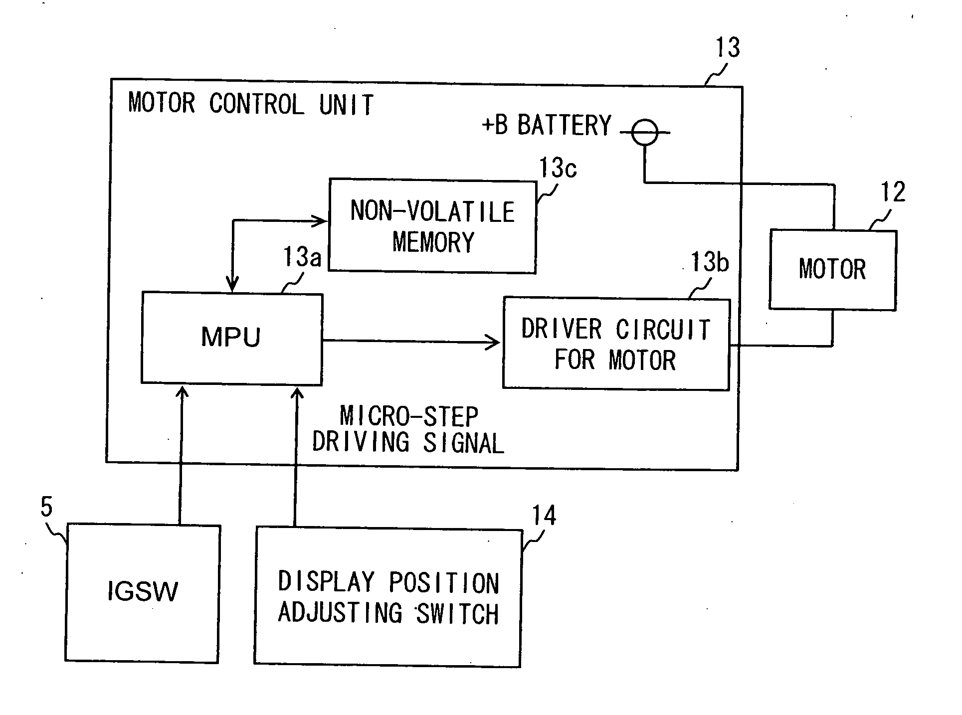
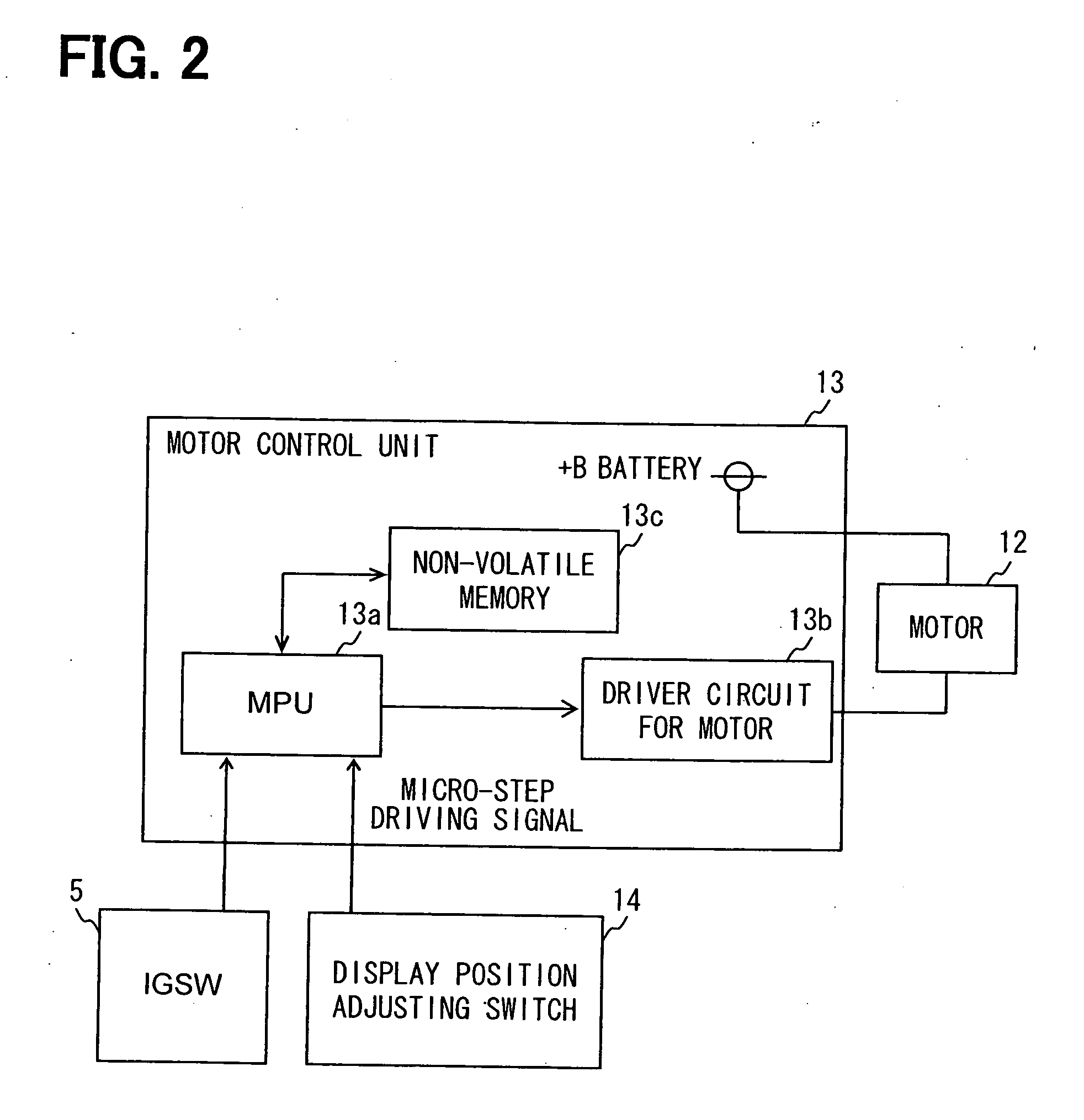
[0037]As shown in FIGS. 1 and 2, the display system 1 is arranged in an instrument panel 2 of the vehicle C and composed of the mirror 11, a step motor 12, a motor control device (unit) 13, and a display position adjusting switch 14.
[0038]The display device 3 is composed of a known display device, for example, a liquid crystal display device having a backlight and arranged in the instrument panel 2. According to the present embodiment, the display device having the backlight is used. However, other types of display d...
second embodiment
[0065]Now, a second embodiment of the present invention will be explained with reference to FIGS. 5A and 5B.
[0066]FIG. 5A is a graph showing a relation between the rotational angle of the rotor of the step motor 12 and the time according to the second embodiment of the present invention. FIG. 5B is a graph showing a relation between the rotational speed of the rotor of the step motor 12 (that is, a changing ratio of the rotational angle with respect to the time) and the time according to the second embodiment. A time point t11 in FIGS. 5A and 5B corresponds to the time point t1 of FIG. 3. A time point t12 in FIGS. 5A and 5B means a time point, at which the rotor of the step motor 12 has reached at the excitation, stable point D3, in other words, the electrical degrees of A phase and B phase of the step motor 12 have reached at such electrical degrees corresponding to the excitation stable point D3.
[0067]During the period that the ignition switch 5 is turned on (until the ignition sw...
third embodiment
[0073]According to a third embodiment of the present invention, when the display position adjusting switch 14 is turned off while the ignition switch 5 is maintained in the ON condition, the step motor 12 is likewise continuously operated until the rotor of the step motor 12 reaches at the next excitation stable point D3. In addition, the rotational speed of the rotor at the time point t1 (at which the display position adjusting switch 14 is turned off) is decreased, and the rotor is rotated in the same direction to that of the rotation at the time point t1.
[0074]Now, the third embodiment of the present invention will be explained with reference to FIGS. 6A and 6B.
[0075]FIG. 6A is a graph showing a relation between the rotational angle of the rotor of the step motor 12 and the time according to the third embodiment of the present invention, while FIG. 6B is a graph showing a relation between the rotational speed of the rotor of the step motor 12 (that is, the changing ratio of the r...
PUM
 Abstract
Description
Claims
Application Information
 - R&D
- Intellectual Property
- Life Sciences
- Materials
- Tech Scout
- Unparalleled Data Quality
- Higher Quality Content
- 60% Fewer Hallucinations
Browse by: Latest US Patents, China's latest patents, Technical Efficacy Thesaurus, Application Domain, Technology Topic, Popular Technical Reports.
© 2025 PatSnap. All rights reserved.Legal|Privacy policy|Modern Slavery Act Transparency Statement|Sitemap|About US| Contact US: help@patsnap.com


