
Apparatus for transmission of energy and/or for transportation of an ion as well as a particle beam device having an apparatus such as this

Inactive Publication Date: 2011-08-11
CARL ZEISS MICROSCOPY GMBH
View PDF21 Cites 8 Cited by
  • Summary
  • Abstract
  • Description
  • Claims
  • Application Information

AI Technical Summary

Benefits of technology

[0025]The impacts of the ions with the gas particles may reduce the radial component of the kinetic energy, thus reducing the amplitude, as already mentioned above, of the macro-oscillation, and the ions may be focused on the transport axis of the container. The axial component of the kinetic energy ensures that the ions pass through the container along the transport axis of the container in the direction of an analysis unit. However, the abovementioned impacts may also decrease the axial component of the kinetic energy, as a result of which the energy of some ions is no longer sufficient to pass completely through the container as far as an analysis unit. A potential gradient is therefore provided on the container. The ions may be moved axially in the direction of the analysis unit by the potential gradient. The potential gradient may be designed such that the potential decreases continuously in the direction of an analysis unit, and has a potential well in the area of one end of the container, which is directed at an analysis unit. The ions may pass through the container and in the process transmit their energy to the gas particles, until they rest in the potential well.
[0026]The first multipole alternating field, for example the first quadrupole alternating field, and the second multipole alternating field, for example the second quadrupole alternating field, may be formed electrically by the first printed circuit board and the second printed circuit board. As already mentioned above, the system described herein provides, for example, for the first multipole alternating field and the second multipole alternating field to be identical. It is advantageous for the apparatus according to the system described herein to be of simple design, and for it to be possible to connect its elements easily. Contact is made with individual elements on the first printed circuit board and on the second printed circuit board via conductor tracks which are arranged in the first printed circuit board and in the second printed circuit board. For example, four first printed circuit board electrodes can be used op the first printed circuit board, and / or four second printed circuit board electrodes on the second printed circuit board. Other embodiments provide for the use of more than four first printed circuit board electrodes and / or four second printed circuit board electrodes, for example 8 or 16 first printed circuit board electrodes and / or 8 or 16 second printed circuit board electrodes.
[0030]According to the system described herein, the container may have a free internal area which is considerably larger than a free internal area of a container which is used in systems from the prior art, which systems have quadrupole units in the form of bar electrodes. The larger free internal area may ensure that even ions with large macro-oscillations and large micro-oscillations can be stored without them striking the multipole units. In the case of the system described herein, each multipole unit may include a plurality of printed circuit board electrodes which are at a distance from the transport axis. With the container having the same maximum external dimensions as the prior art, the system described herein therefore makes it possible to provide a large internal area in the container, with a radius (core radius) which is available for free propagation of the ions.
[0032]Yet another embodiment of the apparatus according to the system described herein additionally or alternatively provides for the internal area to be circular and to have a radius (core radius). Provision may also be made for the first multipole unit and / or the second multipole unit to have a longitudinal extent in the direction of the transport axis which, for example, corresponds to the radius, or essentially to the radius. The first multipole unit and the second multipole unit may each be in the form of a segment. As mentioned above, the length of individual segments may be oriented on the core radius. Since the core radius can be chosen to be greater than a core radius of an apparatus from the prior art, this reduces the number of segments required and which should be arranged along a predeterminable distance on the transport axis. This is a further advantage of the system described herein.
[0048]The above transport apparatus according to the system described herein may be particularly suitable for transporting to an analysis unit the ions which have been braked to a thermal energy after energy has been transmitted from an ion to gas particles. In particular, the transport apparatus according to the system described herein may ensure that ions which are arranged in a potential well are transported to an analysis unit. This may be done by moving the potential well axially along the transport axis of the container. The movement may be produced by the first potential and the second potential, which can be predetermined appropriately. No kinetic energy is supplied to the ions with this form of transport. They may remain focused both axially and radially with respect to the transport axis. This makes it easier to inject the ions into an analysis unit.

Problems solved by technology

However, the abovementioned impacts may also decrease the axial component of the kinetic energy, as a result of which the energy of some ions is no longer sufficient to pass completely through the container as far as an analysis unit.

Method used


Image

  • Apparatus for transmission of energy and/or for transportation of an ion as well as a particle beam device having an apparatus such as this
  • Apparatus for transmission of energy and/or for transportation of an ion as well as a particle beam device having an apparatus such as this
  • Apparatus for transmission of energy and/or for transportation of an ion as well as a particle beam device having an apparatus such as this

Examples


Embodiment Construction

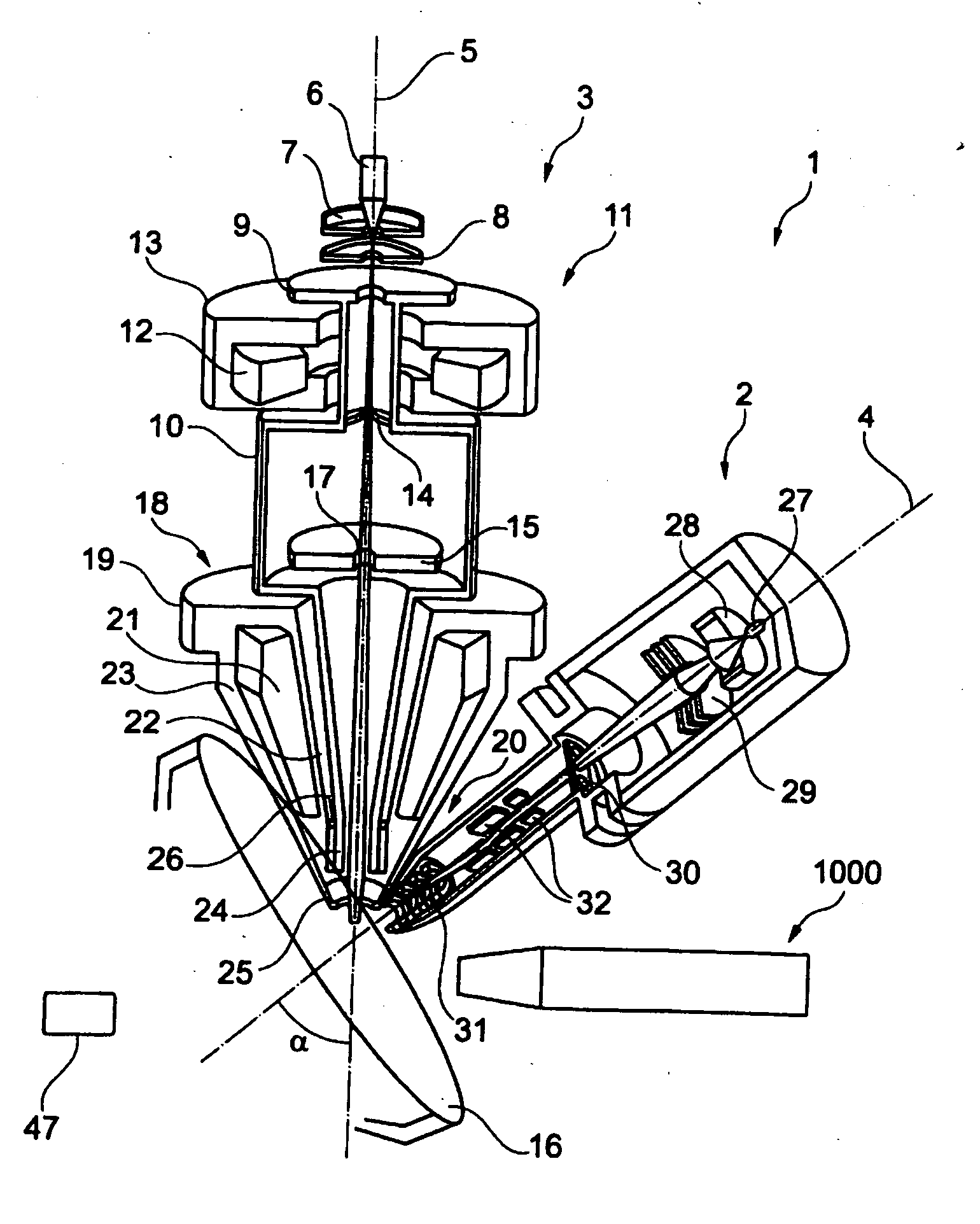
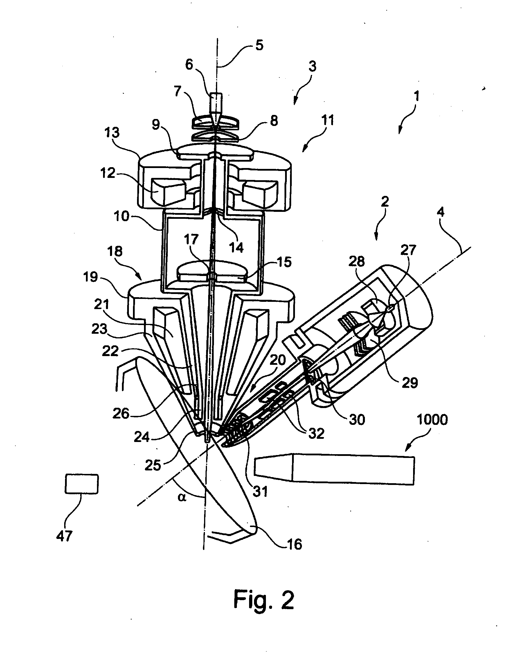
[0080]FIG. 1 shows a schematic illustration of one embodiment of a particle beam device 1 according to the system described herein. The particle beam device 1 has a first particle beam column 2 in the form of an ion beam column, and a second particle beam column 3 in the form of an electron beam column. The first particle beam column 2 and the second particle beam column 3 are arranged on a sample chamber 49, in which a sample 16 to be examined is arranged. It is explicitly noted that the system described herein is not restricted to the first particle beam column 2 being in the form of an ion beam column and the second particle beam column 3 being in the form of an electron beam column. In fact, the system described herein also provides for the first particle beam column 2 to be in the form of an electron beam column and for the second particle beam column 3 to be in the form of an ion beam column. A further embodiment of the system described herein provides for both the first parti...


PUM


Abstract

An apparatus for transmission of energy of an ion to at least one gas particle and / or for transportation of an ion and a particle beam device having an apparatus such as this are disclosed. In particular, a container is provided, in which a gas is arranged which has gas particles, wherein the container has a transport axis. Furthermore, at least one first multipole unit and at least one second multipole unit are provided, which are arranged along the transport axis. The first multipole unit and the second multipole unit are formed by printed circuit boards. Furthermore, an electronic circuit is provided, which provides each multipole unit with a potential, such that a potential gradient is generated, in particular along the transport axis.

Description

TECHNICAL FIELD[0001]This application relates to an apparatus for transmission of energy of an ion to at least one gas particle and / or for transportation of an ion. This application also relates to a particle beam device having an apparatus such as this.BACKGROUND OF THE INVENTION[0002]Particle beam devices have already been in use for a very long time, in order to obtain knowledge about the characteristics and behavior of samples in specific conditions. One of these particle beam devices is an electron beam device, in particular a scanning electron microscope (also referred to in the following text as an SEM).[0003]In the case of an SEM, an electron beam (also referred to in the following text as the primary electron beam) is generated by a beam generator, and is focused by a beam guidance system, in particular an objective lens, onto a sample to be examined. The primary electron beam is passed over a surface of the sample to be examined, in the form of a raster, by a deflection de...

Claims


Application Information

Patent Timeline
IPC IPC(8): H01J49/10H01J3/26B82Y30/00
CPCH01J37/244H01J37/256H01J49/063H01J49/065H01J2237/05H01J49/10H01J2237/2527H01J3/26H01J37/265H01J37/28H01J2237/2449
Inventor GLASMACHERS, ALBRECHTLAUE, ALEXANDERALIMAN, MICHELMANTZ, HUBERTZEILE, ULRIKEDOMER, HOLGER
Owner CARL ZEISS MICROSCOPY GMBH
Learn More