
Hydraulic manifold pump

a manifold pump and hydraulic technology, applied in the direction of fluid couplings, positive displacement liquid engines, couplings, etc., can solve the problems of poor hydraulic oil flow rate through the solenoid valve, poor reliability of conventional systems, and poor flow rate of hydraulic oil

Inactive Publication Date: 2011-08-04
SCHLUMBERGER TECH CORP
View PDF12 Cites 11 Cited by
  • Summary
  • Abstract
  • Description
  • Claims
  • Application Information

AI Technical Summary

Problems solved by technology

These conventional systems, however, do not have a very good reliability due to oil pollution and / or internal leaks.
In addition, the hydraulic oil flow rate can be poor through the solenoid valves used in wireline tools due to the small passageways used in these systems.
This poor rate of flow increases the time that it takes the hydraulic systems to drive the mechanical systems in the well.
Frequent changes in position, and the setting and retracting of hydraulic pistons in such a system lead to an increase in the drilling time that is lost during the completion of these procedures.
This simplicity results in the minimum amount of drilling time lost as a result of the activation of the hydraulic system.

Method used


Image

  • Hydraulic manifold pump
  • Hydraulic manifold pump
  • Hydraulic manifold pump

Examples


Embodiment Construction

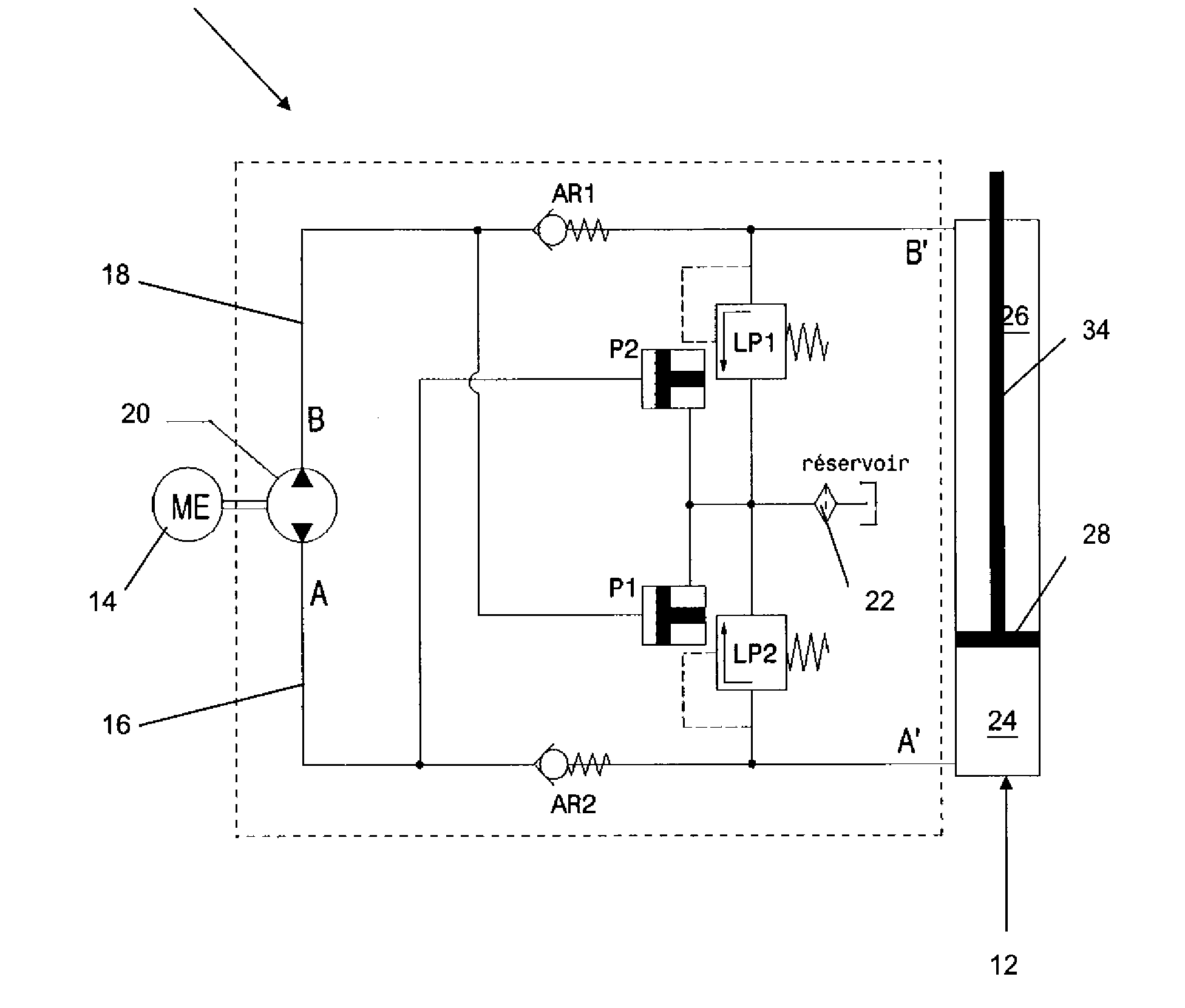
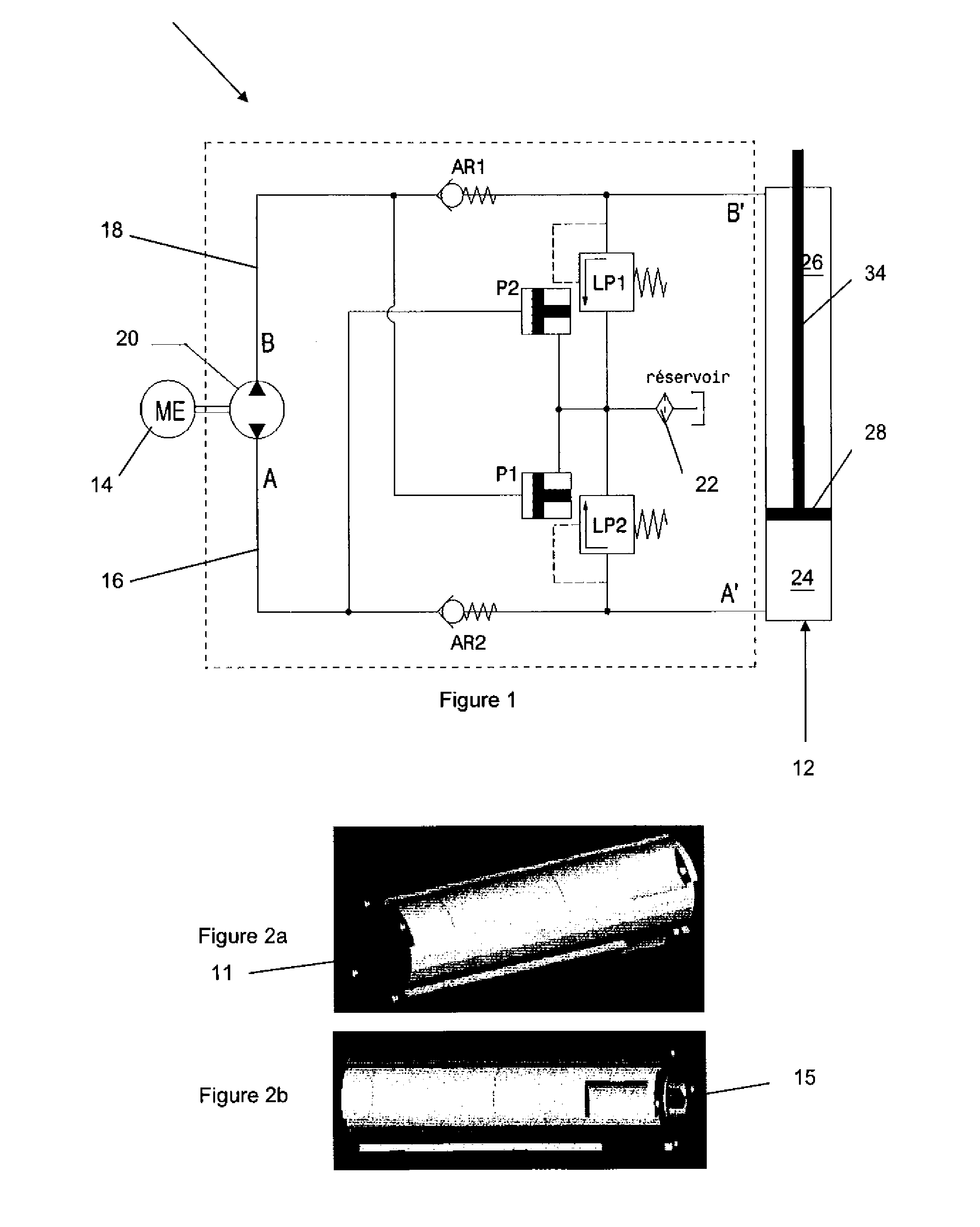
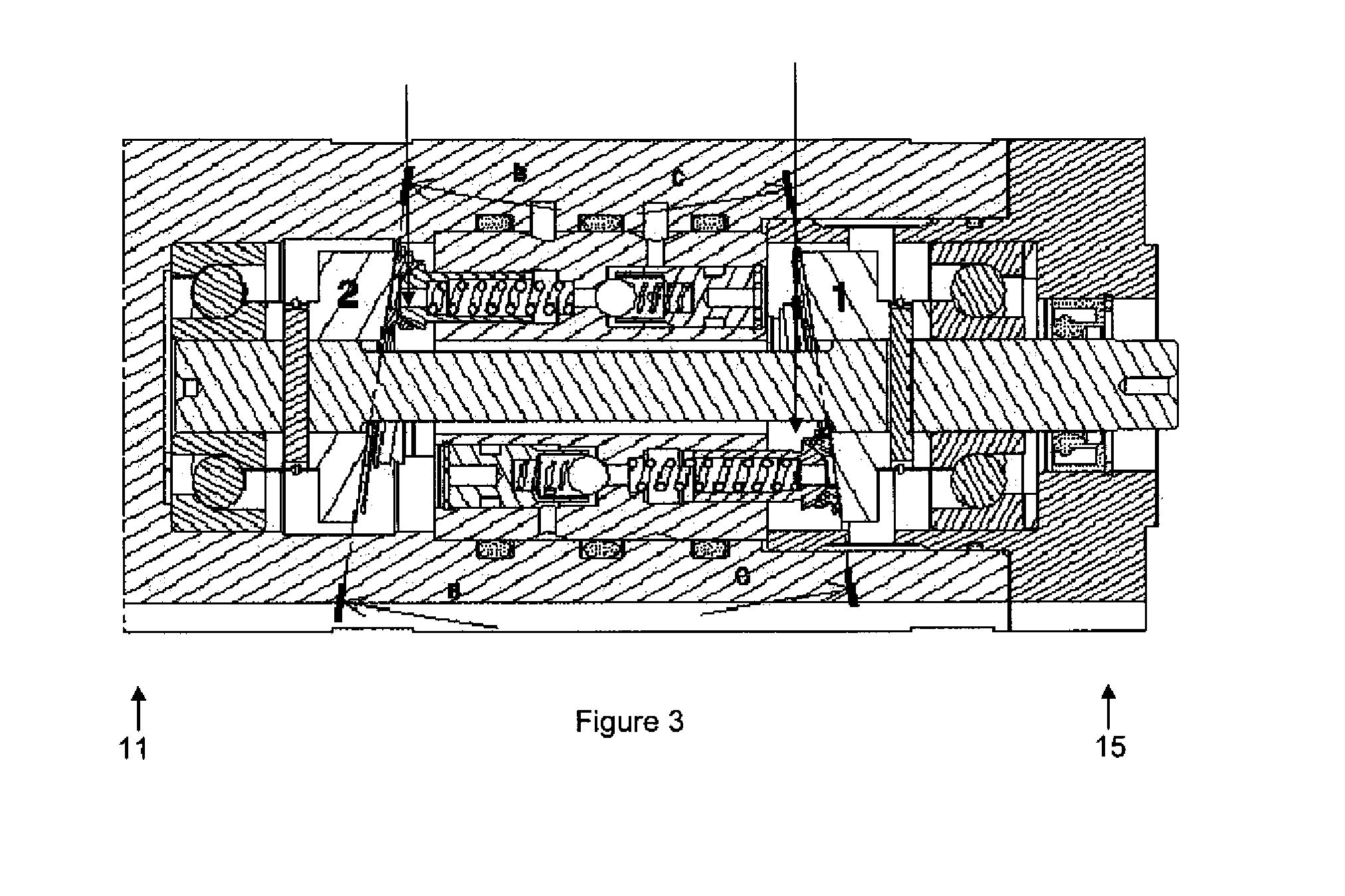
[0034]A preferred embodiment of this invention is illustrated in FIGS. 1 to 6. FIG. 1 shows a schematic diagram of a hydraulic manifold pump 10, according to one embodiment of the invention, which is connected to a double acting hydraulic actuator 12 on one side 11, and an electrical motor 14 on the other side 15. Hydraulic manifold pump 10 is also shown in FIGS. 2a, 2b and 3, and includes a first hydraulic circuit 16 and a second hydraulic circuit 18, both of which are attached to a bidirectional pump mechanism 20 and an internal fluid reservoir 22. Electric motor 14 is a bidirectional motor which produces a rotational speed that controls the fluid flow rate in the first and second hydraulic circuits 16, 18.

[0035]The first hydraulic circuit 16 is indicated using the letter “A” and the second hydraulic circuit 18 is indicated using the letter “B” in FIGS. 1, 5 and 6.

[0036]Hydraulic actuator 12 has two hydraulic chambers 24 and 26, which are connected to manifold pump 10 and separate...


PUM


Abstract

A hydraulic manifold pump comprising a housing in which is located a first hydraulic circuit and a second hydraulic circuit. A bidirectional motor connectable to the first hydraulic circuit and the second hydraulic circuit, the bidirectional motor being able to activate the first hydraulic circuit when operable in a first direction, and being able to activate the second hydraulic circuit when operable in a second direction. The hydraulic manifold pump further compromises a hydraulic actuator having two hydraulic chambers being connectable to the first hydraulic circuit and to the second hydraulic circuit, and both the first and second hydraulic circuits being connected to and able to vent into a fluid reservoir.

Description

CROSS-REFERENCE TO RELATED APPLICATIONS[0001]The present application is based on and claims priority to GB Application No. 0722931.3, filed 23 Nov. 2007; and International Patent Application No. PCT / EP2008 / 009698, filed 17 Nov. 2008. The entire contents of each are herein incorporated by reference.TECHNICAL FIELD[0002]This invention relates to a hydraulic manifold pump. More particularly, the invention relates to a hydraulic manifold pump which may be used to drive a mechanical system in a well.BACKGROUND ART[0003]Conventional hydraulic systems that are used to drive mechanical systems in down-hole applications in wells, such as oil or gas wells, mainly employ two or more hydraulic solenoid valves to orient the flow in the hydraulic lines. These conventional systems, however, do not have a very good reliability due to oil pollution and / or internal leaks. In addition, the hydraulic oil flow rate can be poor through the solenoid valves used in wireline tools due to the small passagewa...

Claims


Application Information

Patent Timeline
Patent Type & Authority Applications(United States)
IPC IPC(8): F16D31/00
CPCF04B1/28F04B49/002F04B23/02F04B17/03E21B23/03F15B7/006F15B7/08F04B49/005
Inventor KOTSONIS, SYPROCANTIN, GILLES
Owner SCHLUMBERGER TECH CORP
Learn More