Optical Transmission and Reception System, and Optical Receiver

a technology of optical transmission and reception system, applied in the direction of electromagnetic transceivers, polarisation multiplex systems, multi-component communication, etc., can solve the problem of difficult compensation of waveform degradation, and achieve the effect of preventing interference in communication

Inactive Publication Date: 2011-07-28
HITACHI LTD
View PDF4 Cites 22 Cited by
  • Summary
  • Abstract
  • Description
  • Claims
  • Application Information

AI Technical Summary

Benefits of technology

[0006]By passing through optical fiber transmission line, optical signal waveform is degraded by chromatic dispersion, polarization mode dispersion and the like. These waveform degradations constitute a factor of increasing a bit error in transmission, and constitute a hindrance in communications. However, these degradations can be compensated using optical compensators, compensating circuits which include a digital signal processing technology or the like on a receiving side.

Problems solved by technology

These waveform degradations constitute a factor of increasing a bit error in transmission, and constitute a hindrance in communications.
Further, PDL is an attenuation of a polarization component of an optical signal which is generated to a certain specific polarization axis, which constitutes a hindrance particularly against transmission of a polarization-multiplexed optical signal.
The waveform degradations are difficult to be compensated for even by an optical device or a digital signal processing circuit, and a problem is posed thereby in an optical transmission system.

Method used


Image

  • Optical Transmission and Reception System, and Optical Receiver
  • Optical Transmission and Reception System, and Optical Receiver
  • Optical Transmission and Reception System, and Optical Receiver

Examples


first embodiment

1. First Embodiment

[0054]First, an explanation will be given of an optical transmission and reception system according to a first embodiment of the present invention.

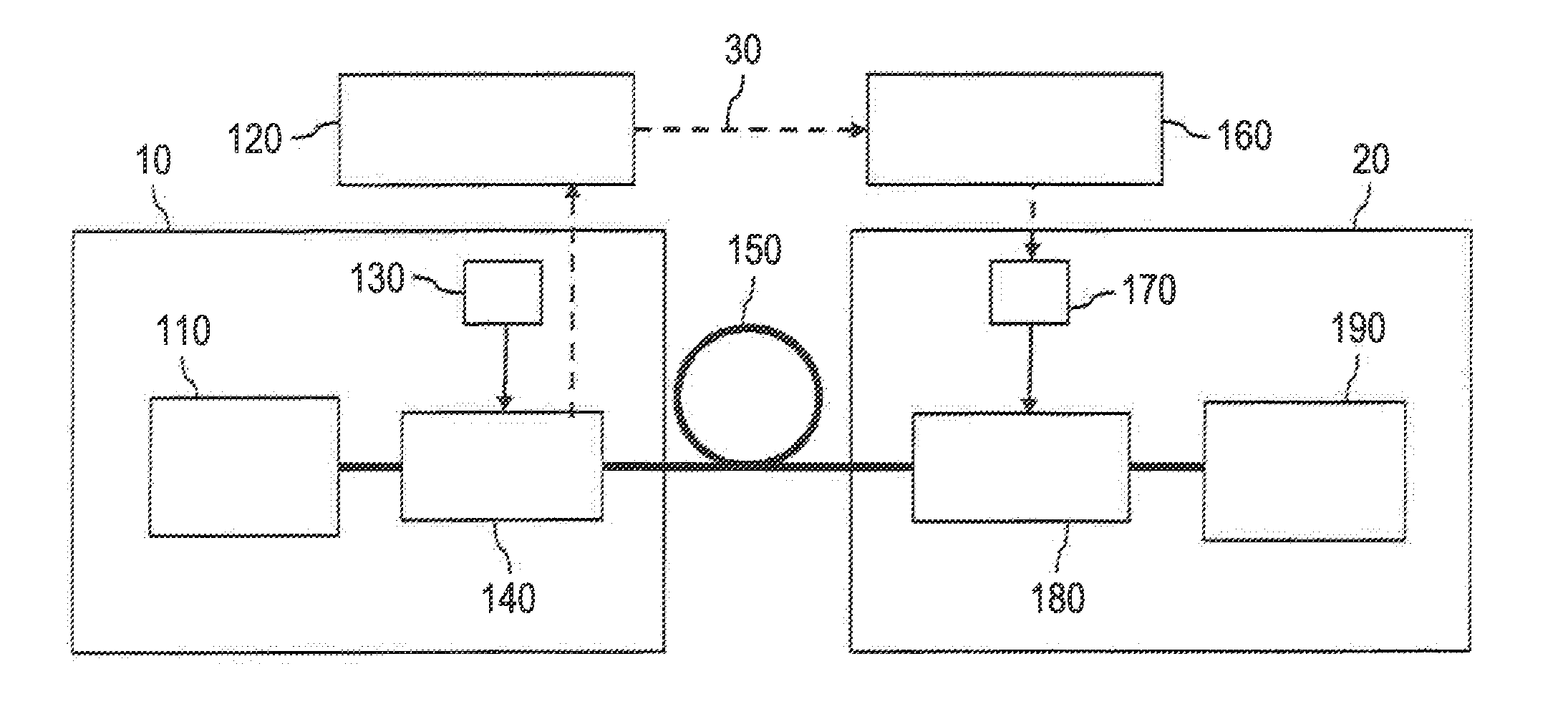
[0055]FIG. 1 is a diagram of a constitution of an optical transmission and reception system according to the first embodiment. As shown by the drawing, the optical transmission and reception system according to the first embodiment includes an optical transmitter 10 of transmitting an optical signal and an optical receiver 20 of receiving are optical signal, a polarization scrambler information acquiring part 120, a polarization descrambler controlling part 160, an optical fiber transmission line 150, and a control network 30. The optical transmitter 10 and the optical receiver 20 are connected by the optical fiber transmission line 150 and the control network 30.

[0056]The optical transmitter 10 includes an optical transmitting part 110, a polarization scrambler driver 130, and a polarization scrambler 140.

[0057]The opt...

second embodiment

2. Second Embodiment

[0089]Next, an explanation will be given of an optical transmission and reception system according to a second embodiment.

[0090]FIG. 8 is a diagram of a constitution of an optical transmission and reception system according to the second embodiment, of the present invention. As shown by the drawing, the optical transmission and reception system according to the second embodiment includes the optical transmitter 10 of transmitting an optical signal and the optical receiver 200f receiving the optical signal, the polarization scrambler information acquiring part 120, a polarization scramble canceling signal processing part controlling part (polarization scramble canceling control part) 530, optical fiber transmission line 150, and the control network 30. The optical transmitter 10 and the optical receiver 20 are connected by the optical fiber transmission line 150 and the control network 30.

[0091]The optical transmitter 10 includes the optical transmitting part 110,...

third embodiment

3. Third Embodiment

[0116]Next, an explanation will be given of a wavelength multiplexing optical transmission and reception system according to a third embodiment of the present invention.

[0117]FIG. 11 is a diagram of a constitution of the wavelength multiplexing optical transmission and reception system according to the third embodiment of the present invention. As shown by the drawing, the wavelength multiplexing optical transmission and reception system according to the third embodiment includes a wavelength multiplexing optical trans fitter 40 of transmitting a wavelength-multiplexed optical signal, a wavelength multiplexing optical receiver 50 of receiving the wavelength-multiplexed optical signal, the polarization scrambler information acquiring part 120, the polarization scramble canceling signal processing part controlling part 530, the optical fiber transmission line 150, and the control network 30. The wavelength multiplexing optical transmitter 40 and the wavelength multi...


PUM


Abstract

An optical signal of an optical transmission part is brought into a high-speed polarization scrambling state by a polarization scrambling part, and transmitted to en optical fiber transmission line as the optical signal from the optical transmitter. The optical signal passing through the optical fiber transmission line is inputted to an optical receiver. The optical signal inputted to the optical receiver is converted into an electric signal by a polarization dependent photoelectric detection part. The converted electric signal is inputted to a digital signal processing part having a polarization scrambling cancel part of canceling the polarization scrambling state by a digital signal processing operation. At the digital signal processing part, the polarization scrambling state of the electric signal is canceled, and a data signal is outputted.

Description

CLAIM OF PRIORITY[0001]The present application claims priority from Japanese patent application JP 2010-016779 filed on Jan. 28, 2010, the content of which is hereby incorporated by reference into this application.FIELD OF THE INVENTION[0002]The present invention relates to an optical transmission and reception system and an optical receiver, particularly relates to an optical transmission and reception system which includes an optical transmitter having a polarization scrambler, and an optical receiver of canceling a high-speed polarization scrambling of an optical signal from the optical transmitter and the optical receiver.BACKGROUND OF THE INVENTION[0003]In recent years, traffic in the internet continues increasing rapidly, and a demand for a high transmission capacity of a core network has been increased. To meet the demand in an existing 10 Gbps wavelength division multiplexed transmission system, the upgrade from a 10 Gbps optical signal to a 40 Gbps optical signal or a 100 G...

Claims


Application Information

Patent Timeline
Patent Type & Authority Applications(United States)
IPC IPC(8): H04B10/00H04B10/077H04B10/2507H04B10/2513H04B10/2569H04B10/40H04B10/50H04B10/532H04B10/548H04B10/58H04B10/60H04B10/64H04B10/66H04J14/00H04J14/04H04J14/06
CPCH04B10/532H04B10/60H04B10/611H04B10/2572H04B10/6162H04J14/06H04B10/6161H04B10/65
Inventor KOTAKE, HIDEAKIKIKUCHI, NOBUHIKOMANDAI, KOHEI
Owner HITACHI LTD
Why Eureka
Try Eureka