Display device and electronic apparatus

a technology of electronic equipment and display device, which is applied in the field of display devices, can solve the problems of not solving the essential problem, exhibiting a significantly low visibility in the outdoor environment, and low image quality, and achieves excellent visibility and high visibility

Active Publication Date: 2011-07-28
SEMICON ENERGY LAB CO LTD
View PDF99 Cites 27 Cited by
  • Summary
  • Abstract
  • Description
  • Claims
  • Application Information

AI Technical Summary

Benefits of technology

[0036]According to the invention, a display device with excellent visibility can be provided by controlling the number of gray scales of an image to be displayed in accordance with the intensity of outside light. That is, a display device which exhibits high visibility in various environments can be provided, in the wide range from, for example, dark places or indoors (e.g., under a fluorescent lighting) to outdoors (e.g., under the sunlight).

Problems solved by technology

However, although a liquid crystal panel exhibits excellent visibility in the indoor environment with an illuminance of 300 to 700 lx, it has a problem in exhibiting a significantly low visibility in the outdoor environment with an illuminance of 1,000 lx or higher.
There is a panel called a reflective liquid crystal panel which has a structure where the outside light is reflected by a pixel electrode; however, it has low image quality under an indoor fluorescent lighting; therefore, it cannot solve the essential problem.
That is, it has been impossible to ensure high visibility in various environments in the range from, for example, dark places or indoors (e.g., under a fluorescent lighting) to outdoors (e.g., under the sunlight).

Method used


Image

  • Display device and electronic apparatus
  • Display device and electronic apparatus
  • Display device and electronic apparatus

Examples


embodiment mode 1

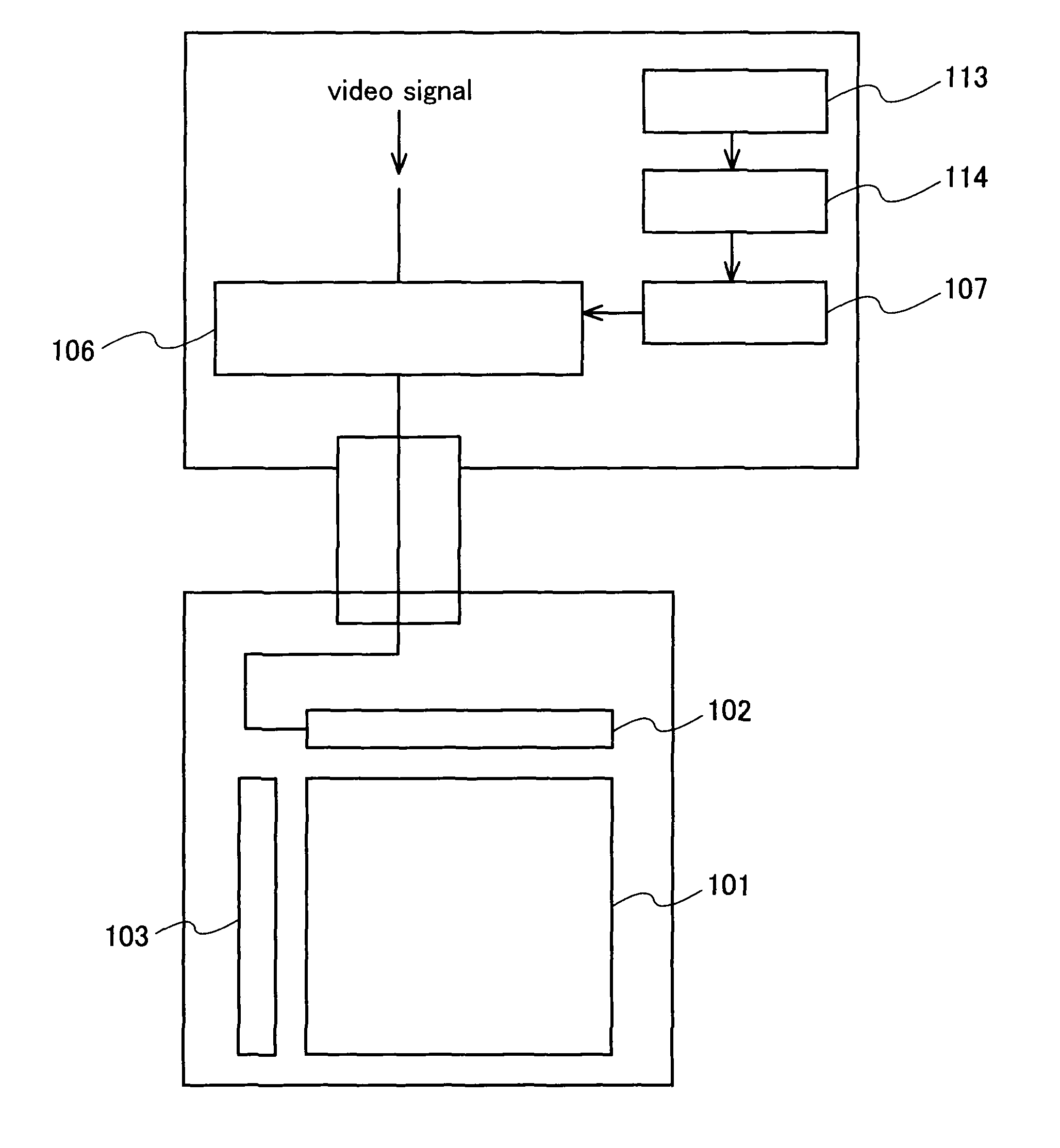
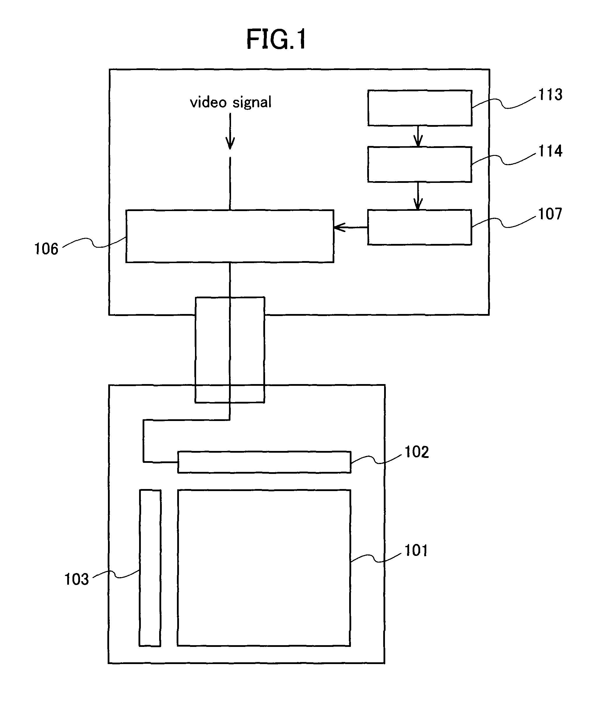
[0078]FIG. 1 shows a schematic view of a display device. A source driver 102 and a gate driver 103 are disposed in order to drive a pixel array 101. The source driver 102 receives video signals. Note that number of the source driver 102 and the gate driver 103 may be more than one.

[0079]An optical sensor 113 detects outside light (light from outside that the display device receives), and the output is supplied to an amplifier 114. The amplifier 114 amplifies an electric signal output from the optical sensor 113, and supplies the amplified signal to a controller 107. Note that the amplifier 114 is not required if the electric signal output from the optical sensor 113 is sufficiently large.

[0080]Note that a part or all of the source driver may be provided outside a substrate having the pixel array 101, and for example, it may be constructed of an external IC chip.

[0081]Note also that the amplifier 114 and the optical sensor 113 may be provided over the same substrate as the pixel arra...

embodiment mode 2

[0131]In Embodiment Mode 1, description has been made of the case where a video signal input to the video signal generating circuit 106 has an analog value. Next, description will be made of the case where a signal with a digital value is input.

[0132]FIG. 24 shows a schematic view of a display device. A video signal input to the source driver 102 is generated in accordance with each display mode, in a circuit 2306 for generating video signals in accordance with each display mode (hereinafter simply referred to as a video signal generating circuit 2306). The video signal generating circuit 2306 is controlled by a controller 2307. The video signal generating circuit 2306 receives an original video signal. Then, the video signal generating circuit 2306 generates a video signal corresponding to each display mode based on the original video signal, and outputs the signal to the source driver 102.

[0133]An optical sensor 2313 detects outside light (light from outside that the display devic...

embodiment mode 3

[0149]In this embodiment mode, a driving method of a pixel in an analog mode will be described.

[0150]FIGS. 16A and 16B show the relationship between a voltage applied to a driving transistor and a light-emitting element, and a current flowing therein. FIG. 16A shows a circuit of a driving transistor 631 and a light-emitting element 632. The driving transistor 631 and the light-emitting element 632 are connected in series between a wire 633 and a wire 634. Since the wire 634 has a higher potential than the wire 634, a current flows from the driving transistor 631 to the light-emitting element 632.

[0151]The driving transistor 1706 in FIG. 15 corresponds to the driving transistor 631 in FIG. 16A, and the light-emitting element 1707 in FIG. 15 corresponds to the light-emitting element 632 in FIG. 16A.

[0152]FIG. 16B shows the relationship between a gate-source voltage (i.e., absolute value) of the driving transistor 631 and a current flowing in the driving transistor 631 and the light-em...


PUM


Abstract

To provide a display device whose display can be recognized even in dark places or under the strong outside light. The display device performs display by controlling the number of gray scales in accordance with the intensity of outside light, which means a display mode can be switched in accordance with the data to be displayed on the display screen. A video signal generation circuit is controlled in each display mode in such a manner that it directly outputs an input video signal with an analog value, outputs a signal with a binary digital value, or outputs a signal with a multivalued digital value. As a result, gray scales displayed in pixels are timely changed. Accordingly, clear images can be displayed while maintaining high visibility in various environments, in the wide range from, for example, dark places or indoors (e.g., under a fluorescent lighting) to outdoors (e.g., under the sunlight).

Description

BACKGROUND OF THE INVENTION[0001]1. Field of the Invention[0002]The present invention relates to a display device having a display screen for displaying text, still images, moving images, and the like. In addition, the invention relates to a technique for improving the visibility of a display screen in various usage environments.[0003]2. Description of the Related Art[0004]In recent years, a so-called self-luminous display device is attracting attention, which has pixels each formed with a light-emitting element such as a light-emitting diode (LED). As a light-emitting element used in such a self-luminous display device, there is an organic light-emitting diode (also called an OLED (Organic Light-Emitting Diode), an organic EL element, an electroluminescence (EL) element, or the like), which has been attracting attention and used for an EL display (e.g., an organic EL display). Since the light-emitting element such as an OLED is a self-luminous type, it is advantageous as compared t...

Claims


Application Information

Patent Timeline
Patent Type & Authority Applications(United States)
IPC IPC(8): H04N5/14G09G5/10H04N5/268
CPCG09G3/2077G09G3/2092G09G3/3275G09G2310/0259G09G2360/144G09G2320/066G09G2330/021G09G2360/02G09G2310/0275
Inventor YAMAZAKI, SHUNPEIKOYAMA, JUNTANADA, YOSHIFUMIOSAME, MITSUAKIKIMURA, HAJIMEFUKUMOTO, RYOTAYANAI, HIROMI
Owner SEMICON ENERGY LAB CO LTD
Why Eureka
Try Eureka