
Plasma treatment apparatus and method

a plasma treatment and apparatus technology, applied in the field of plasma treatment methods and apparatuses, can solve the problems of repeated microdischarges at the same location, poor uniform treatment, and failure to use all available gas for plasma generation of useful chemical species, etc., to achieve more uniform plasma, facilitate randomized electrical breakdown of gas, and increase the probability of dielectric breakdown

Inactive Publication Date: 2011-07-28
COMMONWEALTH SCI & IND RES ORG +1
View PDF7 Cites 6 Cited by
  • Summary
  • Abstract
  • Description
  • Claims
  • Application Information

AI Technical Summary

Benefits of technology

The patent text describes a method and apparatus for plasma treatment of gas permeable materials. The technical effect of the invention is to provide a uniform plasma treatment that prevents burning and damage to the material, while also dispersing and removing ions and plasma by-products that can cause localized plasma microdischarges. The invention uses a strong gas flow to prevent the formation of localized plasma microdischarges and allows for the use of a larger gas volume for generating the plasma. This results in better uniformity of treatment and higher concentration of active species that beneficially modify the surface chemistry of the material.

Problems solved by technology

The ions from each microdischarge do not normally disperse easily and, having lower electrical resistance compared to the surrounding gas, cause the microdischarges to occur repeatedly at the same locations.
This provides very poor uniformity of treatment and fails to use all of the available gas for generation of useful chemical species by the plasma.
Further, the localisation of microdischarges increases the probability of generation of a high temperature instability within the plasma that burns the material to be treated.
The generation of these chemicals changes the nature of the plasma and causes localised excessive absorption of plasma energy and a rapid rise in temperature.
Firstly, ions remaining stationary relative to the electrodes cause localisation of the plasma microdischarges between the electrodes and result in uneven and less effective surface treatment.
Secondly, trapping of ions and plasma-material by-products in a gas permeable material moving relative to the electrodes causes localisation of the plasma relative to the material and can result in burning of the material.
It has further been recognised that the localisation of the plasma microdischarges prevents use of the whole gas volume available in generating the plasma and thus limits the concentration of the active species that beneficially modify the surface chemistry of the material.

Method used


Image

  • Plasma treatment apparatus and method
  • Plasma treatment apparatus and method
  • Plasma treatment apparatus and method

Examples


Embodiment Construction

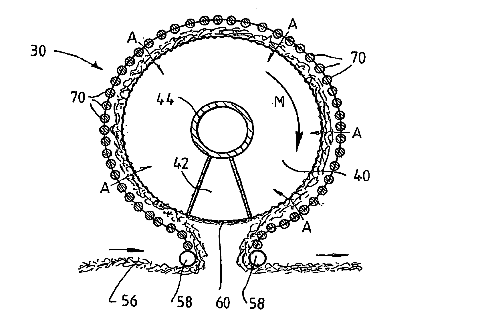
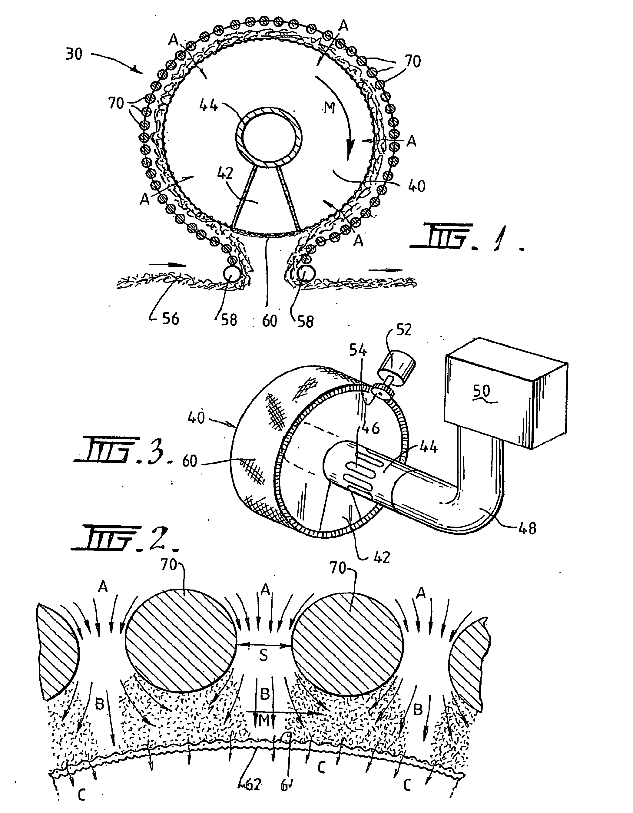
[0056]Referring firstly to FIGS. 1 and 2, it will be seen that the plasma treatment apparatus 30 includes a hollow rotatable drum 40 having a first electrode, in the form of a mesh electrode 60, formed on the curved outer surface of the drum 40. The apparatus 30 further includes a second electrode, formed as a plurality of rod electrodes 70, spaced radially outwardly from the mesh electrode 60.

[0057]The mesh electrode 60 comprises a coarse mesh 62 supporting an overlying layer of fine mesh 64. The fine mesh 64 prevents localisation of plasma microdischarges by providing a large array of potential plasma forming locations, in contrast to the course mesh 62 where the reduced number of potential plasma forming locations would ordinarily lead to localisation of the plasma microdischarges.

[0058]As shown in FIGS. 1 and 3, the drum 40 has a tubular core 44 and a wedge-shaped baffle 42 extending from the core to the outer perimeter of the drum 40. The core 44 extends through the drum 40 and...


PUM

PropertyMeasurementUnit
frequencyaaaaaaaaaa
frequencyaaaaaaaaaa
voltageaaaaaaaaaa

Abstract

A plasma treated gas permeable material is produced by applying an alternating voltage between spaced electrodes, at least one of which is covered with a dielectric barrier and at least one of which comprises a plurality of discrete electrode segments, to generate plasma microdischarges between the spaced electrodes. A gas permeable material is passed between or adjacent to the spaced electrodes. A gas is moved between the electrode segments into and through the space between the electrodes and through the gas permeable material. The gas flows over plasma generation surfaces of the respective electrode segments and is moved at a rate whereby the gas flow between the spaced electrodes is turbulent and so randomises the plasma microdischarges and disperses plasma products that would otherwise give rise to burning instabilities in the gas permeable material, whereby the randomized plasma microdischarges provide a generally uniform plasma treatment of the gas permeable material. Also disclosed is an apparatus for laying out the process.

Description

[0001]This application is a Continuation of Ser. No. 10 / 555,542, filed 4 Nov. 2004, which is a National Stage Application of PCT / AU2004 / 000562, filed 30 Apr. 2004, which claims benefit of Serial No. 2003902139, filed 5 May 2003 in Australia and Serial No. 2003902140, filed 5 May 2003 in Australia and which applications are incorporated herein by reference. To the extent appropriate, a claim of priority is made to each of the above disclosed applications.FIELD OF THE INVENTION[0002]This invention relates to a method and apparatus for the plasma treatment of gas permeable materials, for instance, fibrous materials. The invention is particularly useful when applied to wool.BACKGROUND OF THE INVENTION[0003]Plasma treatment of materials is widely used to alter the surface, characteristics of the material. The treatment is generally useful where it is uniformly distributed over the surface of the material. When applied to woof fibres, plasma treatments are used to oxidize a lipid layer on...

Claims


Application Information

Patent Timeline
Patent Type & Authority Applications(United States)
IPC IPC(8): H05F3/00B01J19/08D06M10/02H05H1/24
CPCB01J19/088B01J2219/0813B01J2219/0815B01J2219/0818B01J2219/083H05H1/24B01J2219/0879B01J2219/0898D06M10/025D06M2101/12B01J2219/0833H05H1/2406H05H1/2431
Inventor FINN, NIALLKVIZ, LADISLAVSCHUTZ, JURGFARMER, ANTHONY
Owner COMMONWEALTH SCI & IND RES ORG
Learn More