Method for managing the exhaust gas circulation circuit of a petrol thermal engine and corresponding recirculation system

a technology of exhaust gas circulation circuit and recirculation system, which is applied in the direction of electric control, machines/engines, mechanical apparatus, etc., to achieve the effect of simple and inexpensiv

Active Publication Date: 2011-07-28
VALEO SYST DE CONTROLE MOTEUR
View PDF12 Cites 4 Cited by
  • Summary
  • Abstract
  • Description
  • Claims
  • Application Information

AI Technical Summary

Benefits of technology

[0012]Thus, the flow rate in one of the lines is regulated in such a way as to increase the pressure difference across the flow regulating valve of the recirculation circuit significantly enough to make it easier to operate the recirculation circuit flow regulating valve, particularly to allow flow rate to be measured more accurately.
[0017]The butterfly valve used for regulating engine speed therefore performs an additional function of compensating for the variation in pressure produced in the inlet line or in the exhaust line for the purposes of increasing the pressure difference.
[0022]This embodiment makes it possible to obtain relatively short response times for the control loop and makes it possible to satisfy the flow rate requirement and / or determine the flow rate in the regulating valve accurately.
[0025]Thus the pressure difference across the valve is increased and the butterfly valve is operated in such a way as to compensate for the variation in pressure (that occurs as a result of this increase) at the engine so as not to disrupt the operation of this engine or negatively affect its performance.

Problems solved by technology

However, at light load, this pressure difference is small and dictates the use of pressure sensors of an accuracy that makes them expensive.

Method used


Image

  • Method for managing the exhaust gas circulation circuit of a petrol thermal engine and corresponding recirculation system
  • Method for managing the exhaust gas circulation circuit of a petrol thermal engine and corresponding recirculation system
  • Method for managing the exhaust gas circulation circuit of a petrol thermal engine and corresponding recirculation system

Examples


Embodiment Construction

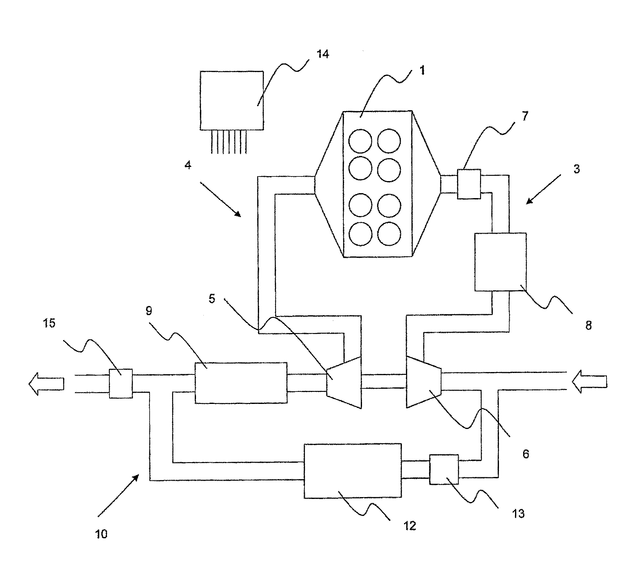
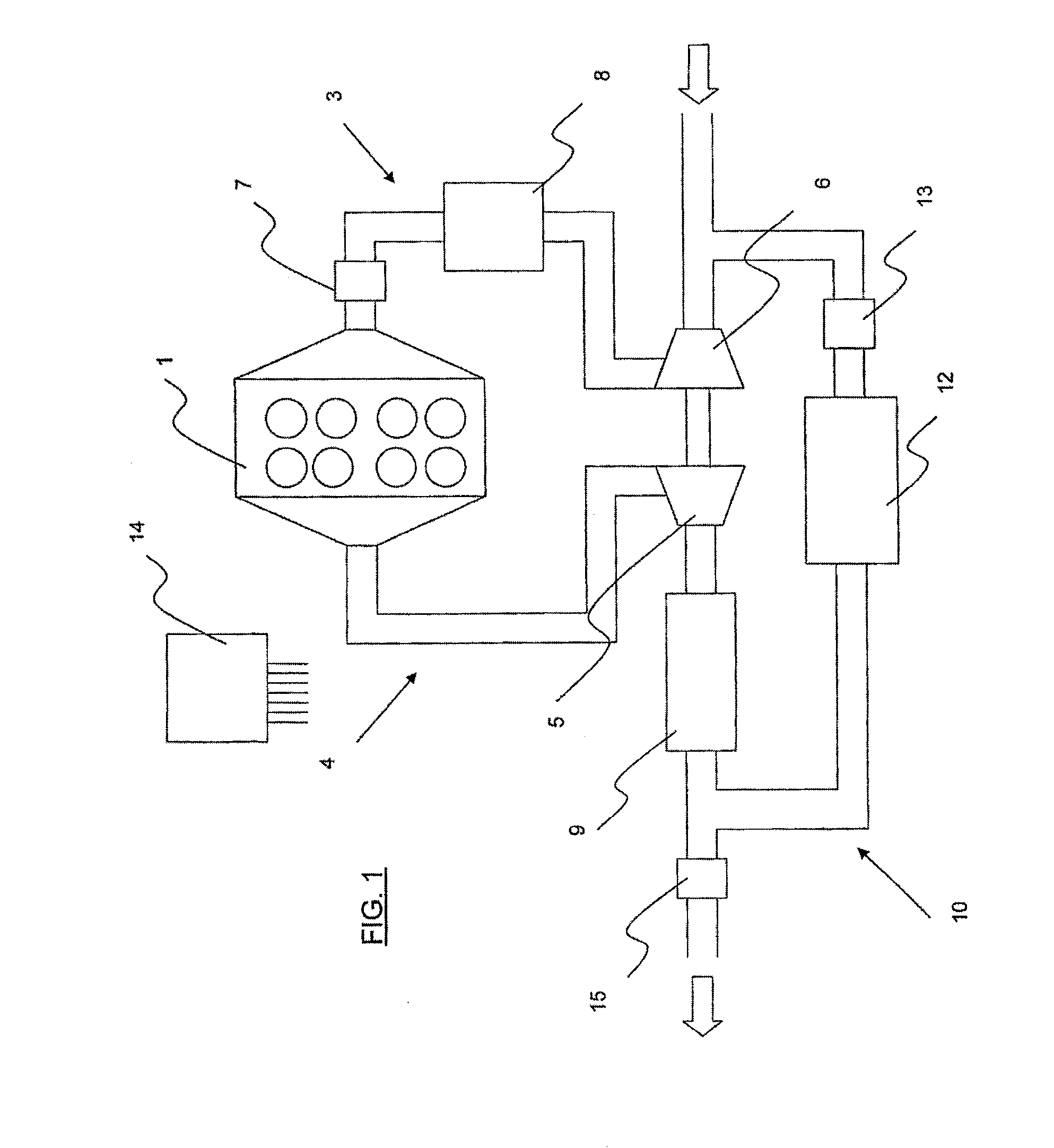
[0033]With reference to FIGS. 1 and 4, the engine comprises an engine block 1 delimiting combustion chambers 2 connected to an inlet line 3 and to an exhaust line 4. Mounted in the exhaust line 4 is a turbine 5 that drives a compressor 6 itself mounted in the inlet line 3.

[0034]Mounted in the inlet line, between the engine block 1 and the compressor 6, are a butterfly valve 7 for regulating engine speed and a charge air cooler 8.

[0035]Mounted in the exhaust line downstream of the turbine 5 is a catalytic converter 9.

[0036]An exhaust gas recirculation (or EGR) circuit 10 is mounted between the exhaust line 4 and the inlet line 3. The EGR circuit 10 has one end connected to the exhaust line 4 downstream of the catalytic converter 9 and one end connected to the inlet line 3 upstream of the compressor 6. The EGR circuit comprises a cooler 12 which, in a way known per se, comprises a cooled path and a non-cooled path between which a bypass member is mounted so as to direct the flow of ex...


PUM


Abstract

The invention relates to a method for managing an exhaust gas recirculation circuit of a petrol thermal engine, the engine including at least one combustion chamber connected to an inlet line and an exhaust line between which extends said recirculation circuit, the recirculation circuit including a flow-rate adjustment valve, wherein said method comprises the step of adjusting flow-rate adjustment valve based on a flow-rate setpoint, said method further comprising the steps of: detecting an operation parameter representative of a pressure difference between an upstream pressure and a downstream pressure relative to the flow-rate adjustment valve, and, after comparing the parameter with a threshold corresponding to a minimum pressure difference, adjusting the flow-rate in at least one of the lines in order to increase the pressure difference.

Description

[0001]The present invention relates to a method for managing an exhaust gas recirculation circuit of an internal combustion gasoline (or petrol) engine and to a system for circulating the gases of such an engine.BACKGROUND OF THE INVENTION[0002]A combustion engine comprises an engine block delimiting combustion chambers which are connected to a fresh gas inlet line and to a burnt gas exhaust line. Mounted in the inlet line is a flow regulating butterfly valve the position of which is determined by the extent to which the throttle pedal of the vehicle is depressed in order to control the rotational speed of the engine. A turbine for driving a compressor mounted in the inlet line is generally mounted in the exhaust line.[0003]It is known practice in internal combustion diesel engines to fit between the inlet line and the exhaust line an exhaust gas recirculation circuit that recirculates exhaust gases to the inlet line. Such a recirculation circuit generally comprises a valve that reg...

Claims


Application Information

Patent Timeline
Patent Type & Authority Applications(United States)
IPC IPC(8): F02M25/07
CPCF02B29/0406F02D41/005F02D2041/0017Y02T10/47F02M25/0718F02M25/0728F02M25/0709F02M26/06F02M26/15F02M26/25Y02T10/40F02M26/00F02B47/08F02D21/08F02D41/00
Inventor VITIELLO, NICOLASPOTTEAU, SEBASTIENCOUSIN, FREDERICVIOLETTE, LOICFOURNIGAULT, DAMIEN
Owner VALEO SYST DE CONTROLE MOTEUR
Why Eureka
Try Eureka