
Dual-connection drain pan

Active Publication Date: 2011-07-28
TRANE INT INC
View PDF18 Cites 4 Cited by
  • Summary
  • Abstract
  • Description
  • Claims
  • Application Information

AI Technical Summary

Benefits of technology

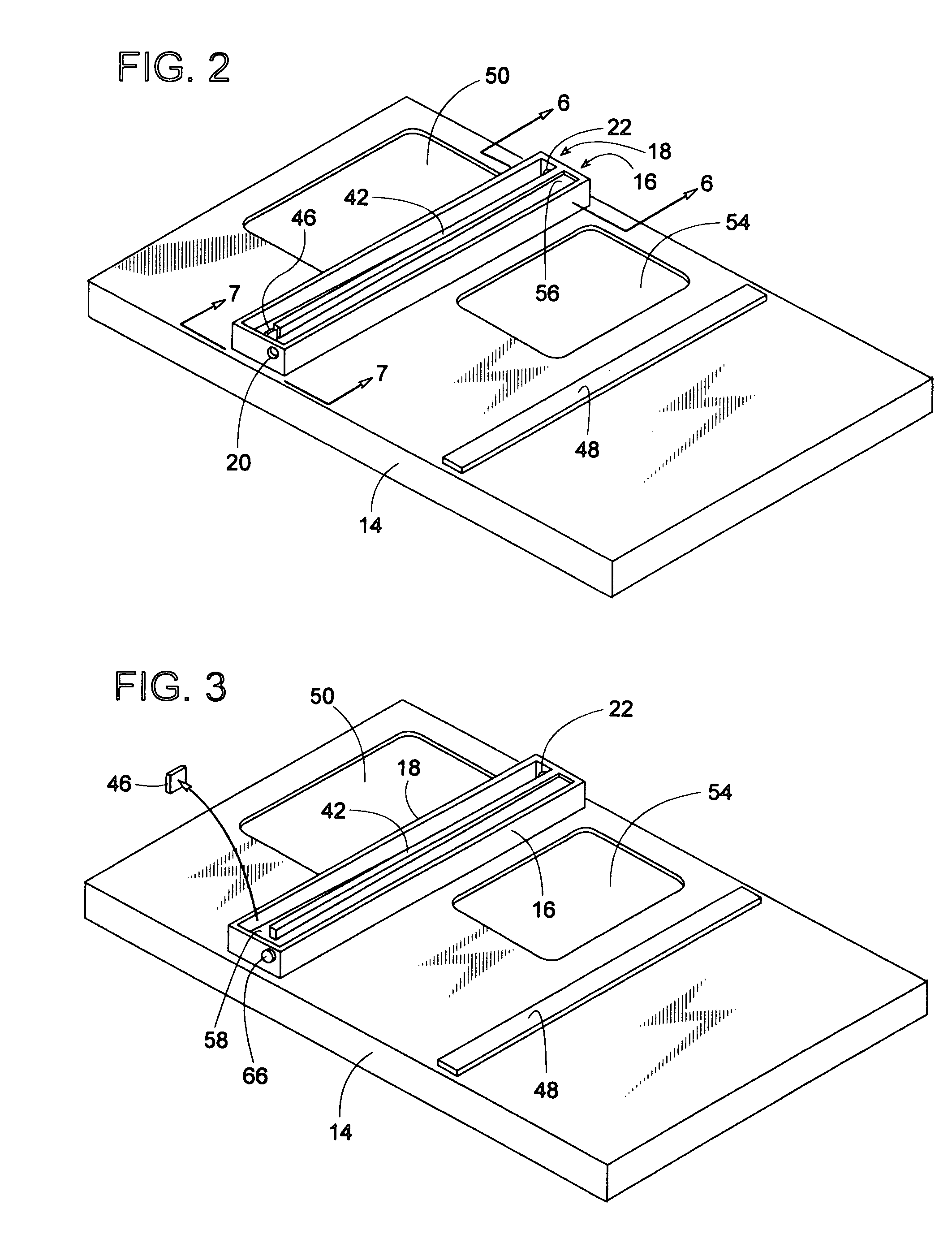
[0013]One or more of these and/or other objects of the invention are provided by a refrigerant system that is subject to condensate. The present invention provides a refrigerant system comprising a cooling coil with a drain pan disposed underneath the coil. The drain pan is at a position to collect condensate draining from the cooling coil. The drain pan includes a first channel and a second channel. The first channel slopes downward in a first direction from a high point to an intermediate area, and the second channel slopes downward in a second direction from the intermediate area to a low point. A dam is selectively disposable at an intact position and a dislodged position such that in the intact position the dam is at the intermediate area to block condensate from flowing from the first channel to the second channel. In the dislodged position, the dam allows condensate to flow from the first channel to the second channel.
[0014]The present invention also provides a refrigerant system subject to condensate, wherein the refrigerant system comprises a cooling coil and a drain pan disposed underneath the cooling coil at a position to collect condensate draining from the cooling coil. The drain pan includes a first channel and a second channel. The first channel slopes downward in a first direction from a high point to an intermediate area. The second channel slopes downward in a second direction from the intermediate area to a low point, wherein the high point is closer to the low point than to the intermediate area. A dam selectively is disposable at an intact position and a dislodged position such that in the intact position the dam is at the intermediate area to block condensate from flowing from the first channel to the second channel, and in the dislodged position the dam is spaced apart from the intermediate area and allows condensate to flow from the first channel to the second channel. A breakable connection connects the dam to the intermediate area such

Problems solved by technology

Although the aforementioned systems are useful in certain applications, they do have their limitation.

Method used


Image

  • Dual-connection drain pan
  • Dual-connection drain pan
  • Dual-connection drain pan

Examples


Embodiment Construction

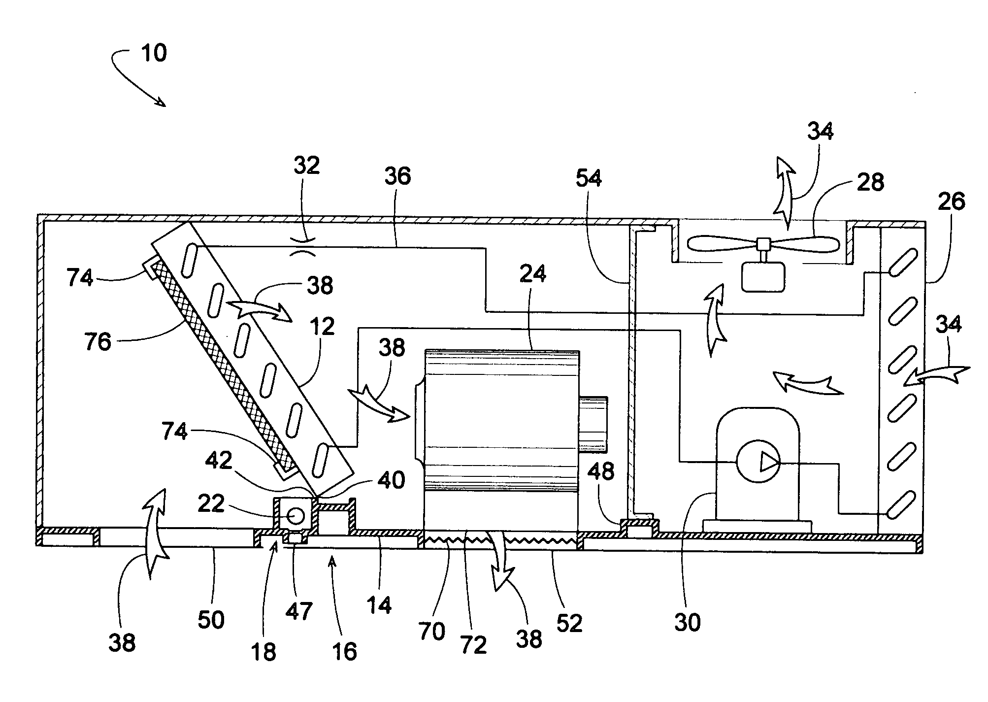
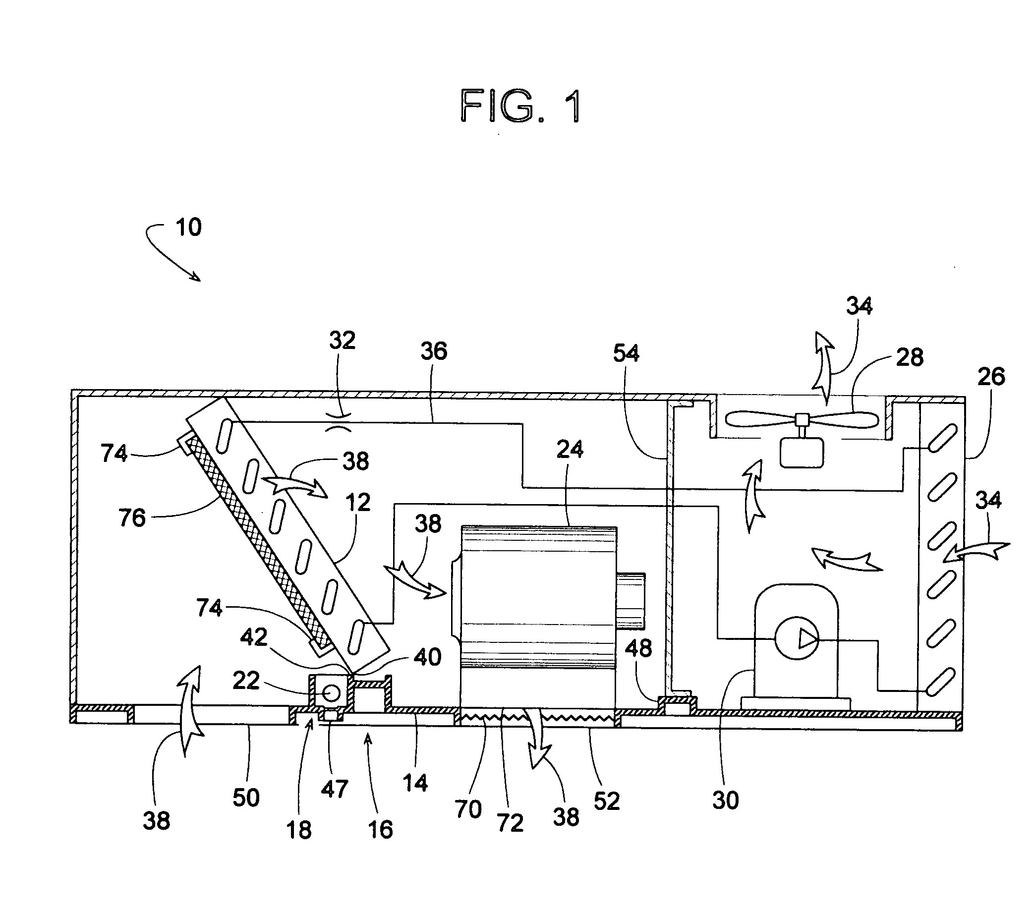
[0026]FIG. 1 illustrates a refrigerant system 10 that includes a cooling coil 12 and a drain pan 14, wherein cooling coil 12 represents any refrigerant evaporator or liquid chilled heat exchanger subject to condensate, and drain pan 14 collects the condensate from coil 12. With further reference to FIGS. 2-9, drain pan 14 includes a first channel 16 and a second channel 18 for directing the collected condensate to either a first drain outlet 20 or a second drain outlet 22, respectively. Having a choice of outlet 20 or outlet 22 for horizontal access, plus perhaps an optional outlet 47 for vertical access, can make it easier to run piping to drain pan 14 during the initial installation of system 10.

[0027]The specific design of system 10 may vary considerably, and the illustrated design is merely for sake of example. In this example, system 10 comprises cooling coil 12, a blower 24, an outdoor coil 26, an outdoor fan 28, a refrigerant compressor 30, and an expansion device 32 (e.g., e...


PUM


Abstract

A refrigerant system includes a dual-connection drain pan for collecting and draining condensate from the exterior surface of a cooling coil. The drain pan includes a first channel and a second channel disposed alongside each other and sloped lengthwise in opposite directions to direct the condensate to either one of two drain outlets at opposite ends of the pan. To drain the condensate to a first outlet, a breakaway removable dam between the two channels is left intact to isolate the second channel from condensate so that the condensate drains from the first channel to the first outlet. Permanently removing the breakaway dam and plugging the first outlet allows condensate to drain from the first channel, into the second channel, and out through the second outlet. In some embodiments, the drain pan, including the two channels and breakaway dam, is formed of a unitary piece of a thermoset polymer.

Description

BACKGROUND OF THE INVENTION[0001]1. Field of the Invention[0002]The subject invention generally pertains to HVAC refrigerant systems and more specifically to a condensate drain pan for such a system.[0003]2. Description of Related Art[0004]Refrigerant systems often include a cooling coil for cooling a stream of air. As the air flows across the coil, moisture from the air condenses on the coil and then drains into a collection pan. The pan usually includes an outlet for draining the condensate from the pan.[0005]Examples of such systems are disclosed in U.S. Pat. Nos. 1,887,313 (Larkin); 3,596,475 (Berger); 4,474,232 (Wright et al.); 5,904,053 (Polk et al.) and 5,966,959 (Steward). Larkin shows a refrigerated showcase with a sloped drip pan, Berger and Wright et al. show heat exchangers that can be installed either in vertical or horizontal positions, Polk et al. discloses a drain pan with alternate drain openings, and Stewart discloses a drain pan that is sloped by way of a lifting ...

Claims


Application Information

Patent Timeline
IPC IPC(8): F25D21/14F25D17/06
CPCF25D21/14F25D2321/145F25D2321/1442
Inventor HAST, STEVEN E.RUBITSKI, GERALD T.
Owner TRANE INT INC
Learn More