
Thermal break system

Active Publication Date: 2016-07-21
THERM O LITE
View PDF0 Cites 4 Cited by
  • Summary
  • Abstract
  • Description
  • Claims
  • Application Information

AI Technical Summary

Benefits of technology

The patent describes adding an extra layer of insulation over an existing window frame before installing a new window. This layer has much lower thermal conductivity than the frame, which allows for better insulation in the new system. This results in a higher energy efficiency rating for the window system with the added insulation.

Problems solved by technology

A significant amount of effort and attention are spent towards increasing the thermal insulating properties of existing windows, as that is a primary source of energy loss in a building.

Method used


Image

  • Thermal break system
  • Thermal break system
  • Thermal break system

Examples


Embodiment Construction

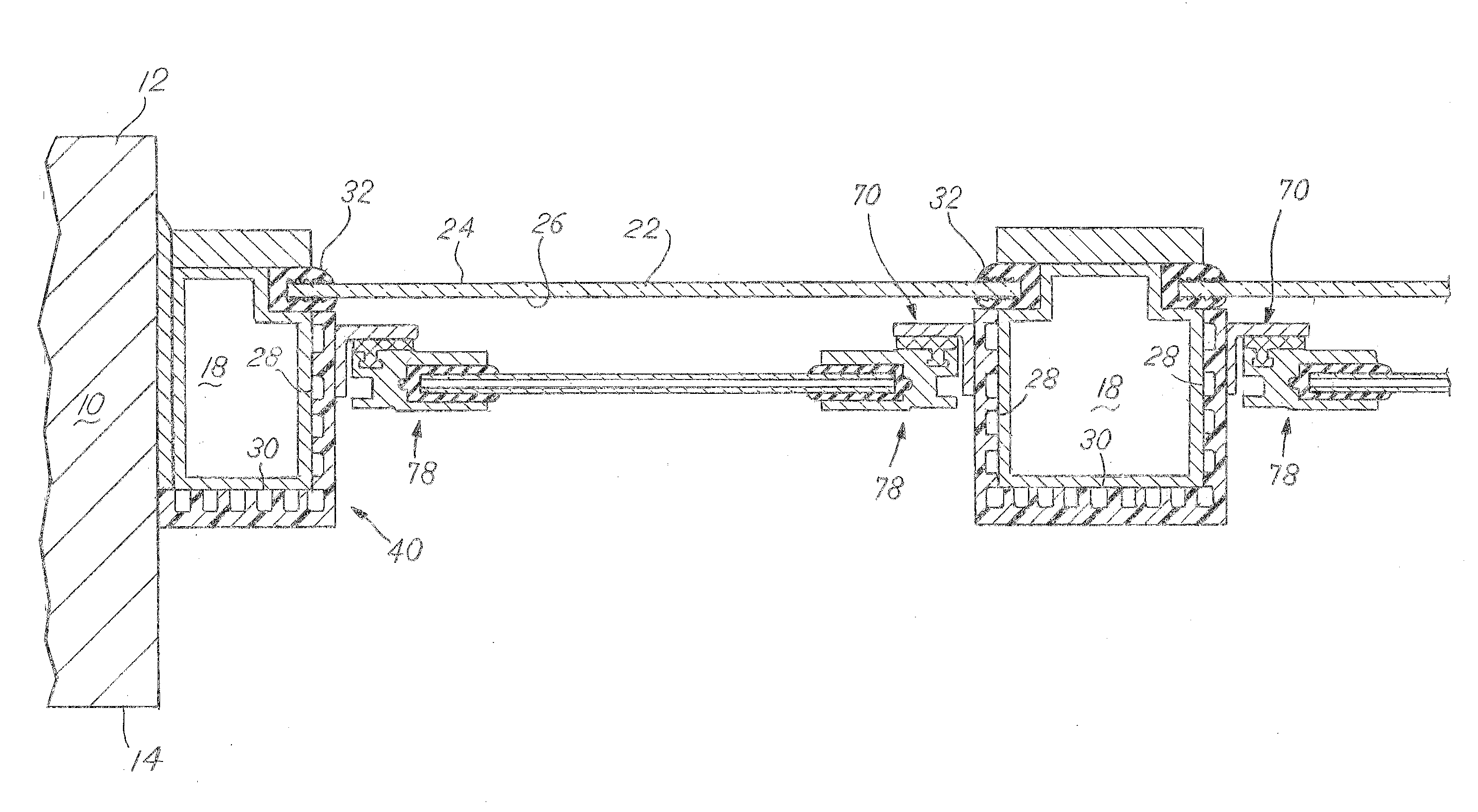
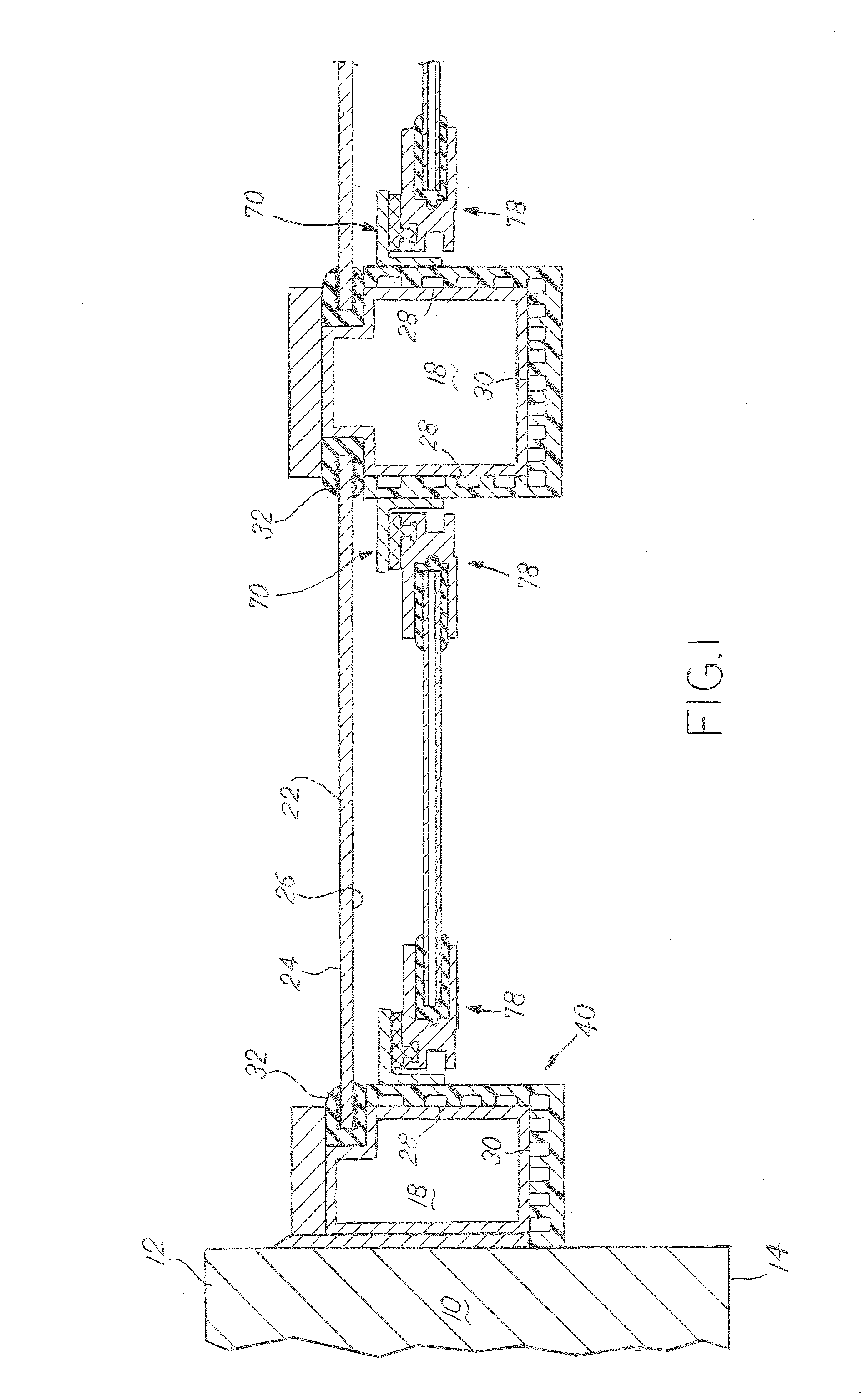
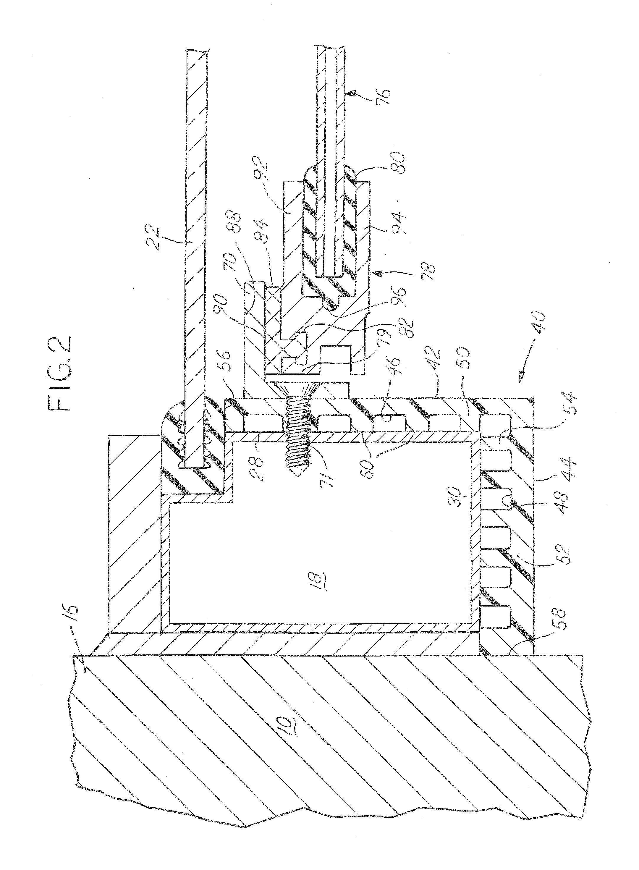
[0011]A building wall 10 has an outside surface 12 and an inside surface14 and an opening defined by a surface 16FIG. 2 that connects the inside surface 14 to the outside surface 12. In the opening, an existing window 20FIG. 4 is mounted, usually to the surface 16. The existing window 20 has an existing frame 18 which mounts an existing window pane 22 as shown in FIGS. 1, 2 and 3. The existing window pane 22 has an outside surface 24 and an inside surface 26. The existing window pane 22 is usually held to the existing frame 18 with a gasket 32 or adhesive. The existing frame 18 is usually sealed to the surface 16 as is commonly known in the art. The existing frame 18 has inside facing surfaces 28 and 30. This retrofit thermal break system is designed to mount on the inside of an existing window 20, specifically the frame 18. The existing frame 18 can also span between two adjacent existing windows 20 as is shown in FIG. 3.

[0012]The retrofit system has a cap 40 which is a single-piec...


PUM


Abstract

A thermal window system is provided where a cap is placed over an existing window frame. A top groove and a bottom groove are attached, along with side stops. A thermal window pane has a sash that surrounds another window pane. The sash fits into the top and bottom groove and overlays the side stops. The sash is held tightly to the side stops using magnetic attraction.

Description

BACKGROUND OF THE INVENTION[0001]This present disclosure relates to retrofit window insulation systems, specifically windows that are added to existing windows and window frames. A significant amount of effort and attention are spent towards increasing the thermal insulating properties of existing windows, as that is a primary source of energy loss in a building. Existing technologies focus on the window pane (by increasing the number or thickness of panes, inert gas, and coatings), but completely neglect the frame. The frame in most office windows is made from aluminum, an excellent conductor of heat. An improved retrofit window solution is needed.SUMMARY OF THE INVENTION[0002]The present disclosure describes an additional layer of insulation that is placed over the existing frame before any retrofit window is installed. The layer has a significantly lower thermal conductivity as compared to the aluminum frame it covers. By covering up the existing window and frame, a higher insula...

Claims


Application Information

Patent Timeline
IPC IPC(8): E06B7/28E06B1/56E06B1/04
CPCE06B7/28E06B1/56E06B1/04E06B7/22E06B1/345E06B3/28
Inventor CHAMPLIN, RICHARD S.
Owner THERM O LITE
Learn More