
Stabilization system for sensors on moving platforms

a technology of stabilization system and sensor, which is applied in the direction of acceleration measurement, antenna details, and reradiation, can solve the problems of more problematic rotational acceleration, insufficient suspension rotation isolation, and unacceptable noise levels, and achieve the effect of optimizing the mass balance of the instrumentation platform and slight bias

Active Publication Date: 2011-07-21
VALE LIMITED
View PDF33 Cites 84 Cited by
  • Summary
  • Abstract
  • Description
  • Claims
  • Application Information

AI Technical Summary

Benefits of technology

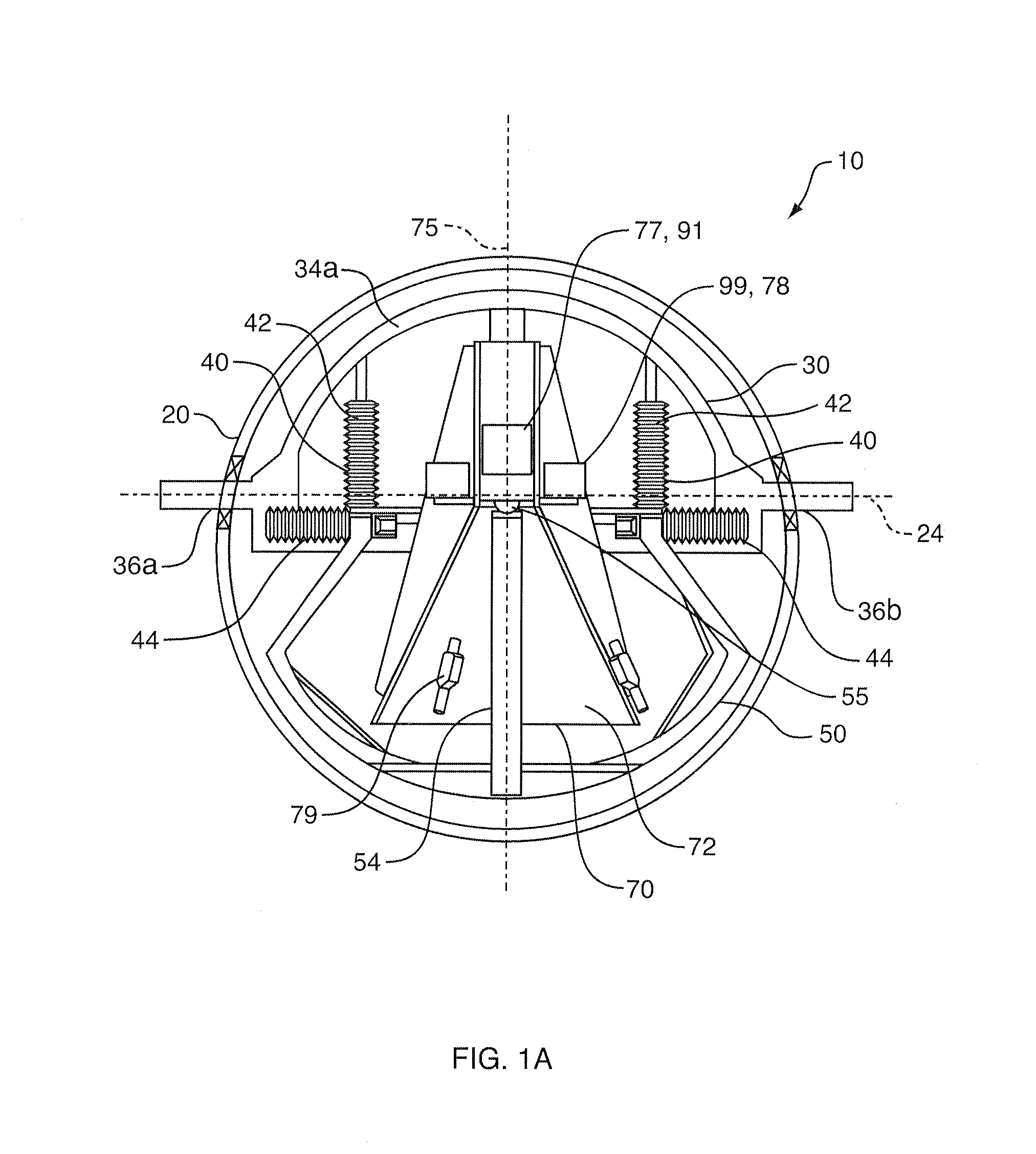
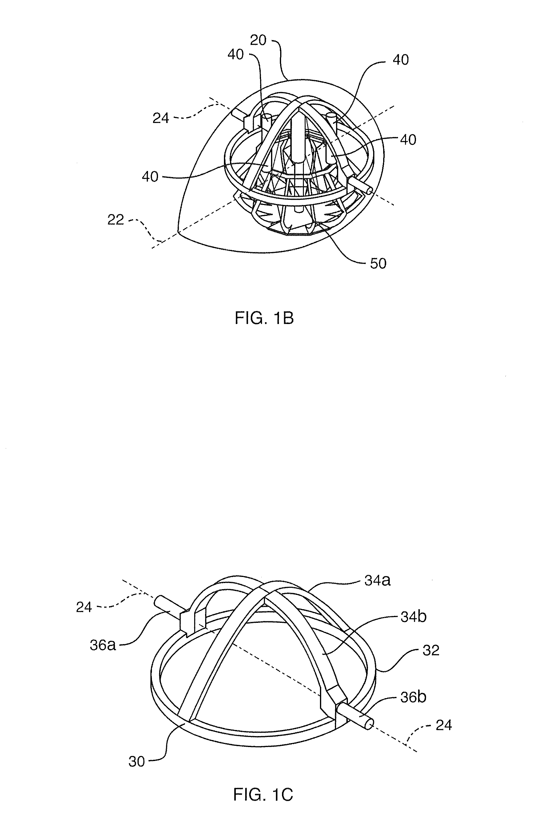
[0031]The housing is coupled to the tow frame. The tow frame bears the innermost two systems and it is coupled to the housing through a horizontal, rotatable axis which allows the tow frame to maintain its pitch angle while changes occur in the angle of attack of the housing during flight. The essential structural component of the tow frame is a roughly horizontal circular ring which supports all the inner systems through a set of vibration isolation dampers. The dampers significantly reduce vibration transmitted to the inner systems from aerodynamic turbulence and from variations in tension in the tow cable.
[0033]The inner-most structure is the instrumentation platform which has the form of an inverted funnel. It is coupled to the base assembly through a single spherical air bearing located at the top of a pedestal attached to the base assembly. The bearing is virtually frictionless. Aided by the platform's high moment of inertia and its almost perfectly balance in all three directions about the point of rotation of the bearing it provides an extremely high level of rotational decoupling between the base assembly and the instrumentation platform. It has about 25 degrees of angular free travel in the roll and pitch directions about support column and has an complete freedom in yaw. It can float totally freely, as there are no power, air or other mechanical connections linking it to the outside.
[0044]The balancing system works by providing an artificial vibration at three fixed frequencies in each of the three vibration directions. The magnetic data from the primary sensors will sense the action of these vibrations if the instrumentation platform is not perfectly balanced. A non-linear optimization algorithm will operate on the PC based in the tow vehicle and it will send commands to the embedded computer to optimize the mass balance of the instrumentation platform. The algorithm provides for the maintenance of a slight bias in the balance so as to maintain the attitude of the platform in a roughly vertical orientation thus keeping it from reaching its limits in roll and pitch.

Problems solved by technology

At frequencies much below 25 Hz, such suspensions do not provide sufficient rotational isolation to permit useful EMI measurements.
Accordingly, attempts using existing systems to lower operating frequencies much below 25 Hz have resulted in unacceptable noise levels.
For EMI measurements, it is the rotational accelerations that are more problematic.
The problem of orientation stabilization is shared by the cinema industry where cameras mounted on moving platforms may be subject to unwanted rotations that render the images unusable.
However, stabilization methods used in the cinematic industry are not precise enough and are also problematic for our purpose.
This approach recognizes that it is unimportant to maintain the direction of the instrumentation package relative to the housing as long as provision is made that the suspension can be kept within its mechanical range of operation.
These all suffer from rotational noise problems to one degree or another, all employ some form of passive sensor rotation control using restoring forces and dampers of one form or another.
None of them operate at frequencies below 25 Hz because the motion-induced noise is too high.
Passive (natural field) airborne electromagnetic measurements suffer from the same susceptibility to motion-induced noise as controlled-source systems at lower frequencies.
Few geophysicists believe Barringer's system could ever work.

Method used


Image

  • Stabilization system for sensors on moving platforms
  • Stabilization system for sensors on moving platforms
  • Stabilization system for sensors on moving platforms

Examples


Embodiment Construction

[0066]Principal Utility of the Invention:

[0067]The present invention is a new airborne bird containing several component systems. Together with its interior systems and while it is being towed from a helicopter or other aircraft, the bird measures three-component magnetic field data across a wide range of frequencies, especially including the low frequency band from 1 Hz to 25 Hz. The principal application of the invention is in geophysical exploration to detect zones of enhanced electrical conductivity (“Conductors”) in the Earth and to characterize the time-varying nature of electrical conductivity in the earth (“Polarization”) through the observed magnetic fields. These time-varying magnetic fields are often diagnostic of mineral and petroleum deposits, lithological and structural variations in ground, aquifers and contamination plumes, and man-made objects such as fences, pipelines, ordnance and treasure.

[0068]The present invention is the first device which will allow a user to ...


PUM


Abstract

A stabilized field sensor apparatus collects field data, in particular magnetic field data, with reduced motion noise. The apparatus includes a tear drop shaped housing, a tow frame in the housing, a plurality of vibration isolating dampers spaced around the frame, a base assembly mounted to the dampers, a support pedestal having a bottom end fixed to the base assembly and an upper free end, a single spherical air bearing connected to the upper free end of the pedestal, an instrument platform with a lower hollow funnel having an upper inside apex supported on the air bearing for a one point support, principal and secondary gyro stabilizers for maintaining pivotal and rotational stability, and at least one field sensor mounted to the instrument platform for collecting the field data while being stabilized against motion noise including vibration, pivoting and rotation from the base assembly, from the tow frame and from the housing. Stabilization of the instrument platform is enhanced by preserving accurate balance through a dynamic balancing system whereby small masses are moved under computer control to maintain the center of mass of the instrument platform at the center of rotation of the spherical air bearing. The dynamic stabilization process is made more precise by actively vibrating the instrument platform by a set of linear vibrators.

Description

FIELD AND BACKGROUND OF THE INVENTION[0001]The invention relates generally to the field of sensor supports, and, in particular, to a new and useful magnetometer stabilization device that facilitates continuous collection of broad-band vector magnetic field data including unique low frequency magnetic measurements in the bandwidth of 1 Hz to 25 Hz, without being affected by motion noise. The invention is particularly useful for mineral resource prospecting using active or passive electromagnetic techniques from air, land or water borne vehicles.[0002]The problem addressed by the invention is the continuous vector measurement of time-varying magnetic fields in the 1 Hz to over 10 kHz frequency range by sensors mounted in a transportable housing towed by an aircraft (often called a bird, a drone or a sonde) or mounted on a land or water vehicle. The magnetic field of interest is created as a result of electromagnetic induction (EMI) by currents at these frequencies flowing through the ...

Claims


Application Information

Patent Timeline
Patent Type & Authority Applications(United States)
IPC IPC(8): G01R33/02
CPCG01V3/165G01R33/022G01V3/16F16F15/00G01C19/16
Inventor POLZER, BENJAMIN DAVIDWEST, GORDON FOXWALKER, PETER WHYTEHURLEY, PETER ANTHONYHOGG, ROBERT LESLIE SCOTT
Owner VALE LIMITED
Learn More