Lubricant supply device and method for operating a lubricant supply device
- Summary
- Abstract
- Description
- Claims
- Application Information
AI Technical Summary
Benefits of technology
Problems solved by technology
Method used
Image

Examples
Embodiment Construction
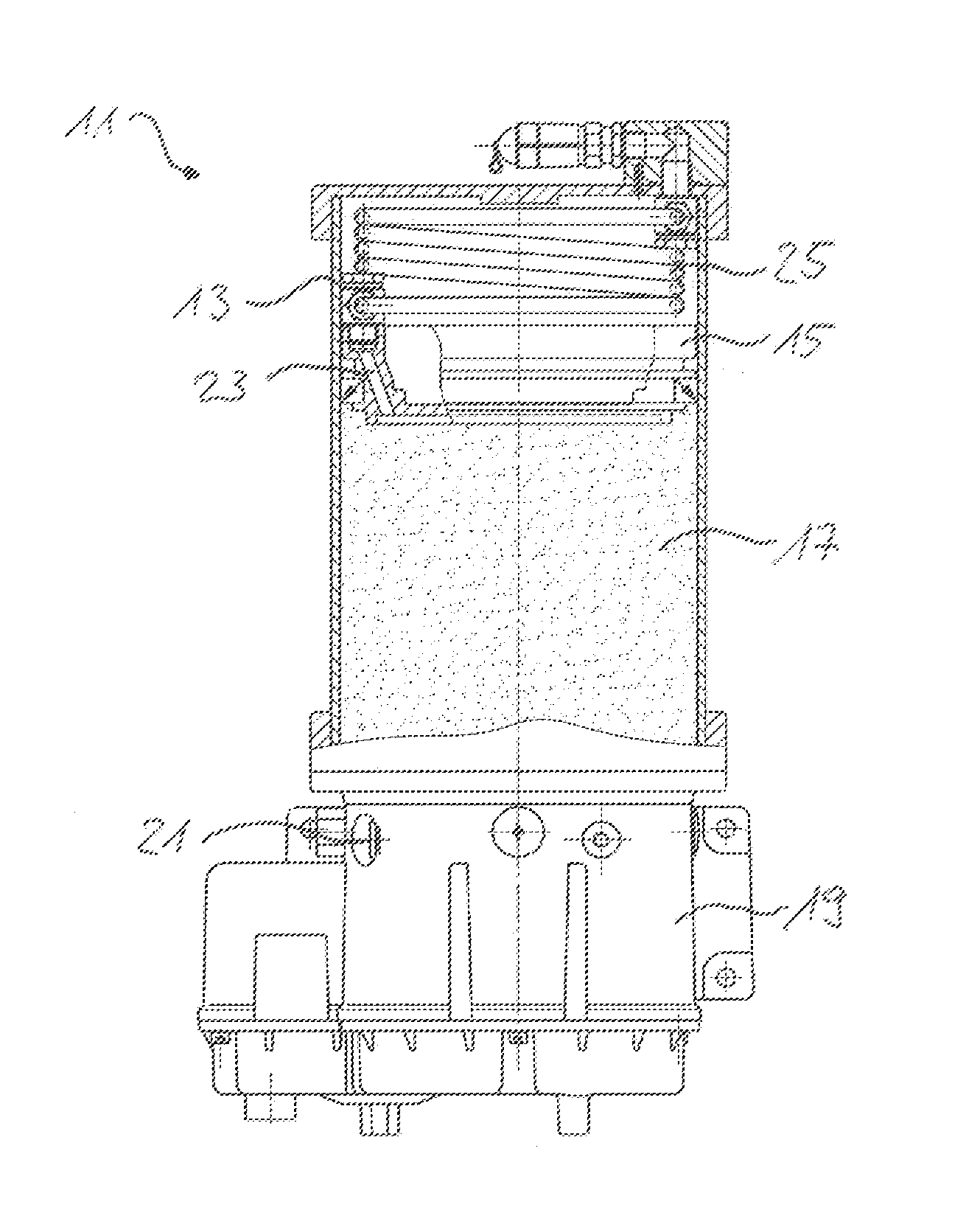
[0037]The embodiments of the prior art and the invention described in the following each relate to the embodiment having a passive piston unit as described in the Related Art section. However, in the alternative, the use of an active piston is also possible in an analogous manner in all the below-described exemplary embodiments.
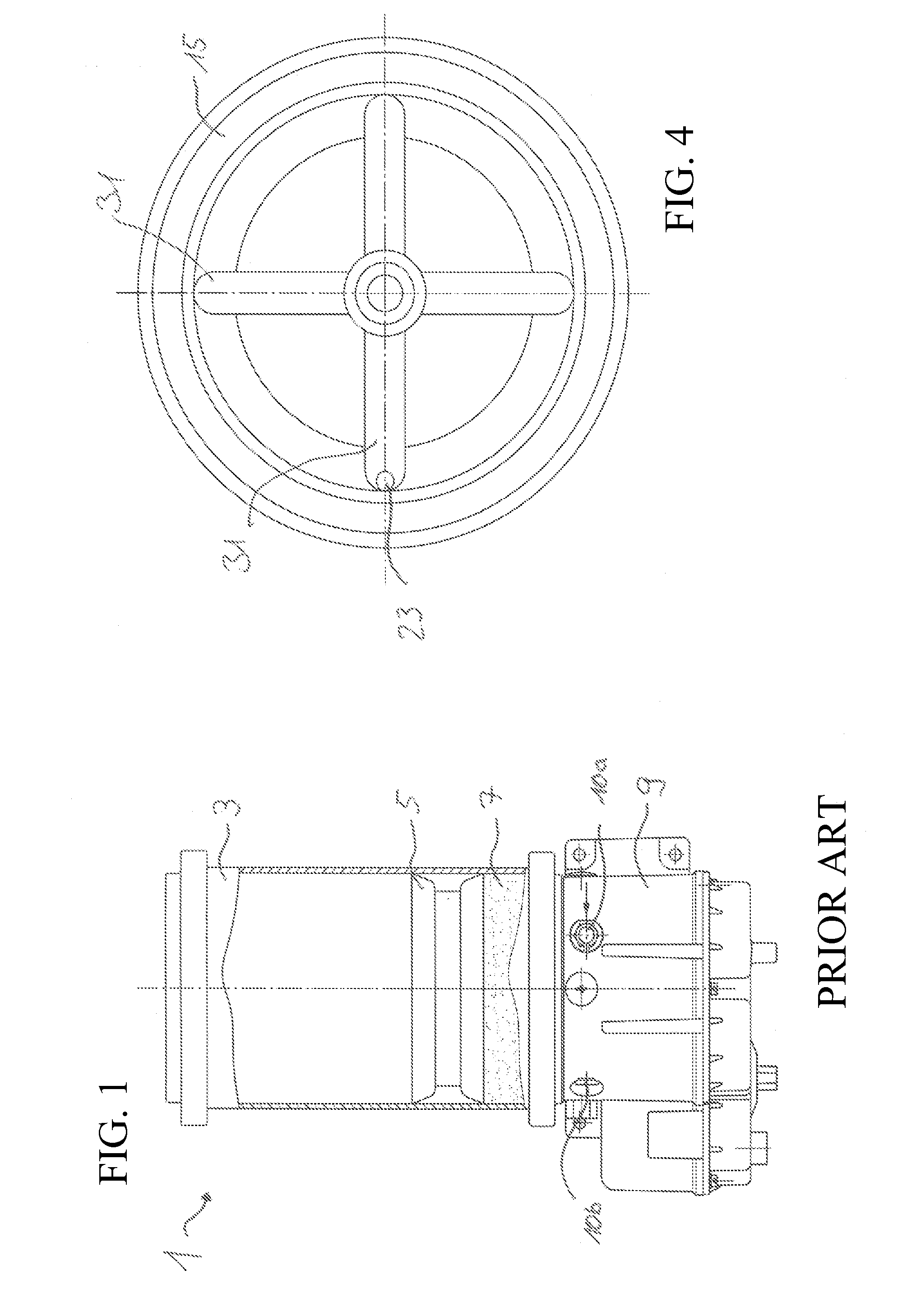
[0038]A lubricant supply device 1 known from the prior art is illustrated in FIG. 1. It comprises a holding tank 3, which is comprised, e.g., of metal, glass or plastic. The holding tank 3 is illustrated in FIG. 1 in a partially-opened manner, in order to make visible components located in the interior. A movable piston 5 is disposed in the holding tank 3. The piston 5 is movable up and down in the holding tank 3. A lubricant chamber 7 is defined by the movable piston 5 and the boundaries of the holding tank 3. A lubricant, e.g., a lubricating grease, is disposed in the holding tank 3. A conveying device 9 is located on the side of the holding tank 3 that is ...
PUM
 Abstract
Description
Claims
Application Information
 - R&D
- Intellectual Property
- Life Sciences
- Materials
- Tech Scout
- Unparalleled Data Quality
- Higher Quality Content
- 60% Fewer Hallucinations
Browse by: Latest US Patents, China's latest patents, Technical Efficacy Thesaurus, Application Domain, Technology Topic, Popular Technical Reports.
© 2025 PatSnap. All rights reserved.Legal|Privacy policy|Modern Slavery Act Transparency Statement|Sitemap|About US| Contact US: help@patsnap.com