Solar Powered Wheel Apparatus

a technology of solar energy and wheel, which is applied in the direction of pv power plants, rider propulsion, cycles, etc., can solve the problems of reducing the efficiency of solar energy conversion into electrical energy by solar devices, reducing the efficiency of rotating rotary objects, and reducing the electrical energy outpu

Inactive Publication Date: 2011-07-21
LEE WILLIAM EDWARD +1
View PDF8 Cites 13 Cited by
  • Summary
  • Abstract
  • Description
  • Claims
  • Application Information

AI Technical Summary

Problems solved by technology

The static solar devices are exposed to sunlight to the extent possible and due to their static or stationary position throughout their operation, tend to heat up resulting in decreased electrical energy out

Method used


Image

  • Solar Powered Wheel Apparatus
  • Solar Powered Wheel Apparatus
  • Solar Powered Wheel Apparatus

Examples


Embodiment Construction

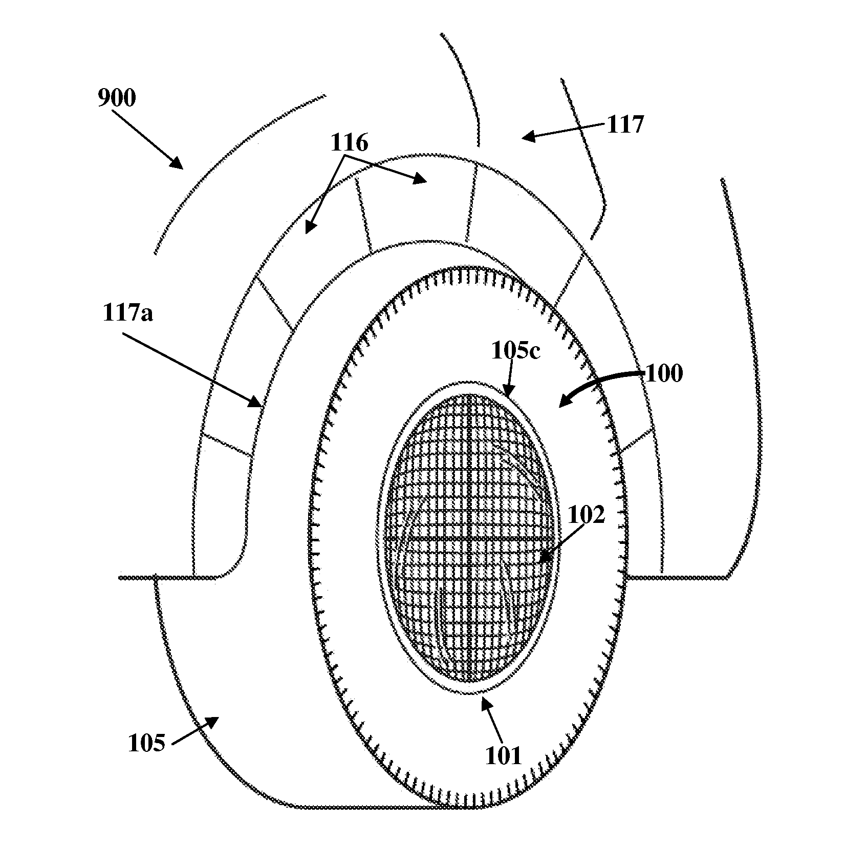
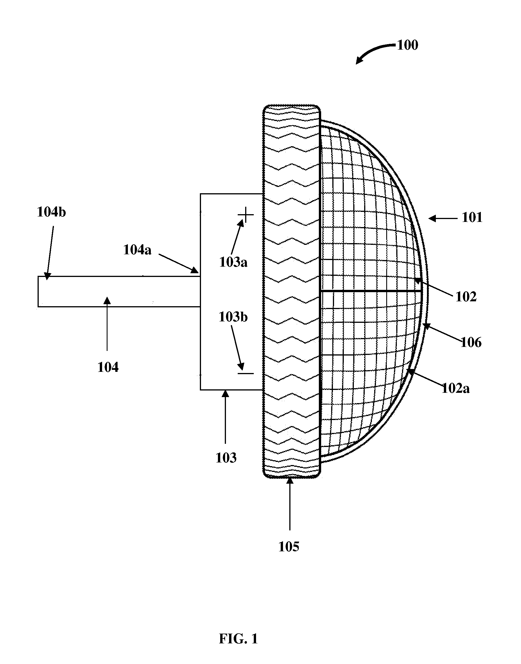
[0060]FIG. 1 exemplarily illustrates a side orthogonal view of a solar powered wheel apparatus 100, where a rotatable element 101 that houses photovoltaic cells 102 is connected to a rotary object 105, for example, a wheel. The solar powered wheel apparatus 100 disclosed herein comprises one or more photovoltaic cells 102, an electric motor 103, and an axial shaft 104. The photovoltaic cells 102 are housed on the rotatable element 101. As used herein, the term “rotatable element” refers to a panel 101 comprising a packaged interconnected assembly of photovoltaic cells 102. The rotatable element 101 is configured in one of multiple profiles, for example, a dome profile, a semi-spherical profile, a conical profile, a flat-ended profile, a trapezoidal profile, a pyramidal profile, and any combination thereof, to house multiple photovoltaic cells 102 in different arrangements as disclosed in the detailed description of FIGS. 8A-8D. The rotatable element 101 is connected to a rotary obje...


PUM


Abstract

A solar powered wheel apparatus comprising one or more photovoltaic cells housed on a rotatable element connected to a rotary object such as a wheel, an electric motor, and an axial shaft, is provided. The electric motor is in electric communication with the photovoltaic cells that power the electric motor and is rigidly connected to the rotatable element that houses the photovoltaic cells. The axial shaft is rotatably connected to the electric motor and rigidly connected to a support structure of the rotary object. The electric motor converts electrical energy produced by the photovoltaic cells into mechanical energy causing the electric motor to rotate about the axial shaft. The rotation of the electric motor rotates the rigidly connected rotatable element that houses the photovoltaic cells. The rotation of the rotatable element housing the photovoltaic cells removes heat from the photovoltaic cells and causes rotation of the connected rotary object.

Description

CROSS REFERENCE TO RELATED APPLICATIONS[0001]This application claims the benefit of provisional patent application No. 61 / 295,800 titled “Rotating Photovoltaic Cells In Wheels”, filed on Jan. 18, 2010 in the United States Patent and Trademark Office.[0002]The specification of the above referenced application is incorporated herein by reference in its entirety.BACKGROUND[0003]Conventional solar apparatuses for rotating a rotary object, for example, a wheel of a vehicle comprise static or stationary solar devices in electric communication with an electric motor. The electric motor generally forms the dynamic part of the solar apparatus executing rotations via a shaft. The static solar devices are exposed to sunlight to the extent possible and due to their static or stationary position throughout their operation, tend to heat up resulting in decreased electrical energy output. Consequently, this leads to a decrease in efficiency of conversion of solar energy into electrical energy by t...

Claims


Application Information

Patent Timeline
IPC IPC(8): B60K16/00H01L31/052
CPCB60K7/0007B62M6/85B60K17/356B60K2007/0038B60K2007/0092B60K2016/003B60Y2200/12B60Y2200/145B60Y2200/148B60Y2200/31B60Y2200/46B60Y2200/52B60Y2200/81B60Y2200/91H01L31/042Y02E10/50Y02T10/90H01L31/02H01L31/02008H02S10/40H02S20/00B60K16/00
Inventor LEE, WILLIAM EDWARDPLENKOWSKI, ROBERT F.
Owner LEE WILLIAM EDWARD
Why Eureka
Try Eureka