
Method and apparatus for rule-based automatic layout parasitic extraction in a multi-technology environment

a technology of automatic layout and rule-based layout, applied in the field of circuit design, can solve the problems of inability to accurately and accurately verify circuit components, and inability to accurately stitch models

Inactive Publication Date: 2011-07-14
CADENCE DESIGN SYST INC
View PDF5 Cites 11 Cited by
  • Summary
  • Abstract
  • Description
  • Claims
  • Application Information

AI Technical Summary

Benefits of technology

The invention provides a method and apparatus for automatically extracting layout objects in a multi-technology environment based on a specified extraction rule and binding them to corresponding solvers based on a specified binding rule. The system includes a rule-based layout extraction engine, a means for selecting a layout object, a means for binding the object to a solver, a means for specifying a boundary condition for the solver, and a means for executing the solver on the object to generate a model. The invention allows for the efficient and accurate extraction of layout objects from electronic circuits, reducing the time and effort required for the design process.

Problems solved by technology

Verification tools addressing entire circuits are often ill-suited to the verification of specialized components of a circuit.
For example, a circuit verification tool may be both inaccurate and slower than a more specialized verification tool when faced with a specialized component.
However, manual stitching of models is error prone.
The manual translation of a solver's output in a format compatible with another solver's input is time-consuming and also error prone.
Furthermore, changes made to the layout in one or more of the fabrics require rerunning the extraction process, which is also time-consuming and error prone in a manual environment because of the many combinations of models required for the simulator or simulation test bench.
Circuits which are embedded in multiple fabrics present additional challenges to verification and simulation.

Method used


Image

  • Method and apparatus for rule-based automatic layout parasitic extraction in a multi-technology environment
  • Method and apparatus for rule-based automatic layout parasitic extraction in a multi-technology environment
  • Method and apparatus for rule-based automatic layout parasitic extraction in a multi-technology environment

Examples


Embodiment Construction

[0036]Reference will now be made in detail to the preferred embodiments of the invention, examples of which are illustrated in the accompanying drawings. The invention may, however, be embodied in many different forms and should not be construed as being limited to the embodiments set forth herein; rather, these embodiments are provided so that this disclosure will be thorough and complete, and will fully convey the concept of the invention to those skilled in the art. In the drawings, the thicknesses of layers and regions are exaggerated for clarity. Like reference numerals in the drawings denote like elements.

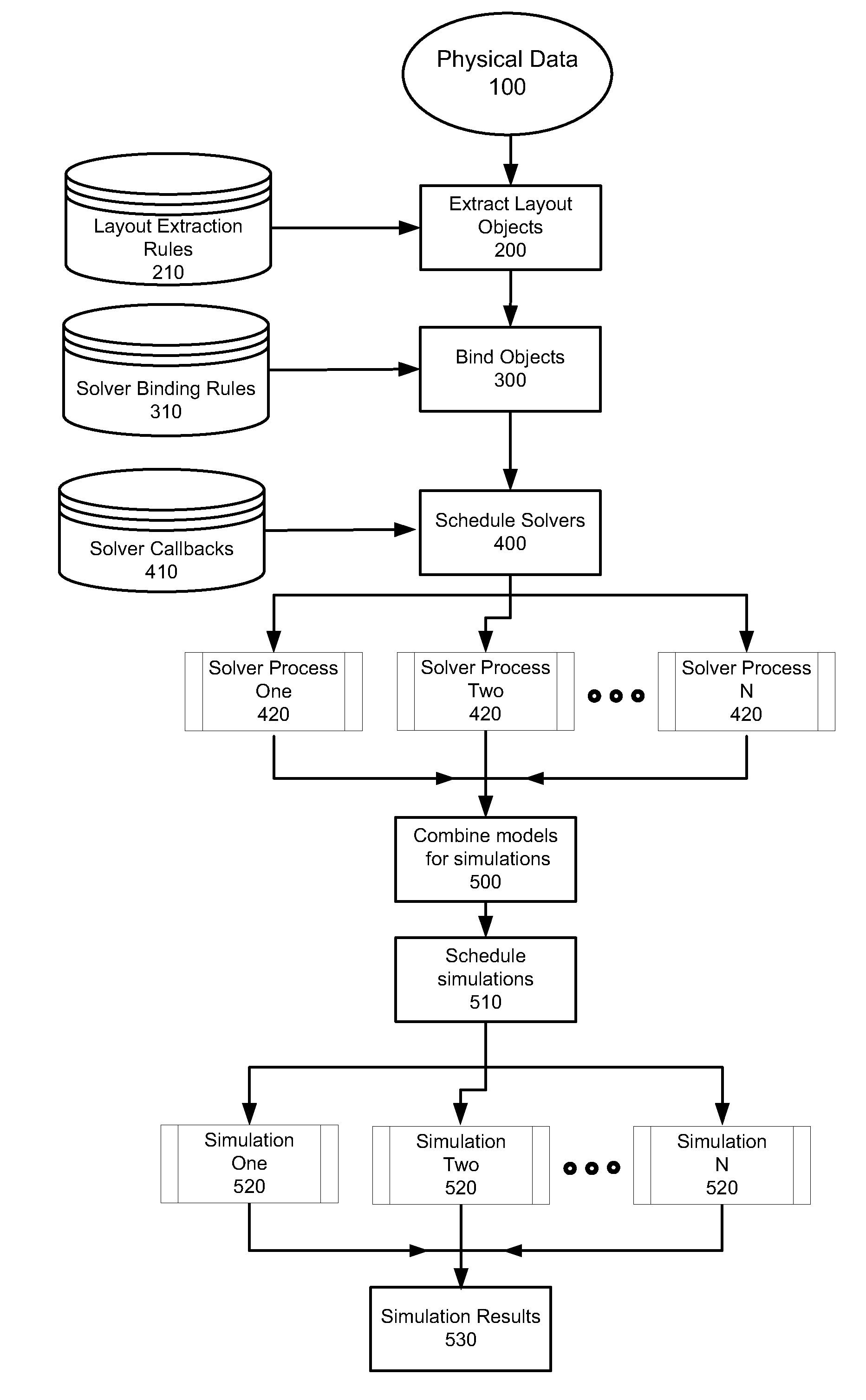
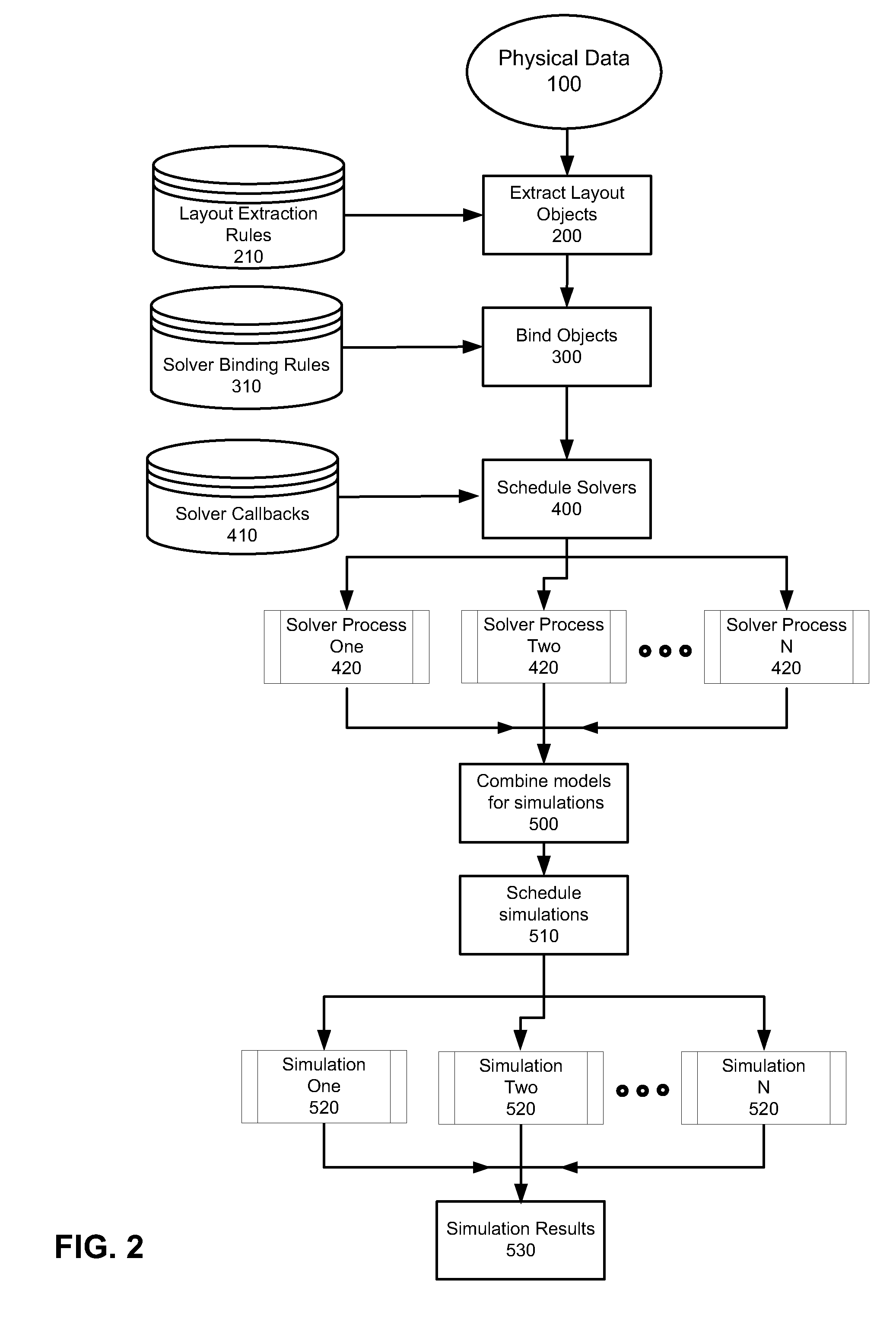
[0037]FIG. 2 shows an exemplary flow chart illustrating a method for automatically integrating multiple layouts for multiple technologies across multiple fabrics according to an embodiment of the invention. Referring to FIG. 2, the process is provided with physical data 100 corresponding to one or more layout including electronic devices or components interconnected in a pres...


PUM


Abstract

A system for extracting a layout from an object in a fabric includes means for providing fabric data to a rule-based layout extraction engine; means for maintaining a layout extraction rule to select a layout object from the fabric data; means for maintaining a binding rule to bind the layout object to a solver; means for maintaining a boundary rule to specify a boundary condition for a solver; and means for executing the solver on the layout object to generate a model of the object.

Description

BACKGROUND OF THE INVENTION[0001]1. Field Of The Invention[0002]The embodiments of the invention relate to circuit design and more particularly to simulating models of parasitic effects in technologies which span multiple fabrics. Although embodiments of the invention are suitable for a wide scope of applications, it is particularly suitable for automatically, under the guidance of user-defined rules, extracting layout objects from a layout spanning multiple fabrics, recognizing custom design patterns in the layout, binding the layout objects to specialized solvers to generate models of parasitic effects, and simulating combinations of the models arising from layout objects which span multiple fabrics.[0003]2. Discussion Of The Related Art[0004]In general, an electronic system include a plurality of integrated circuit chips (IC) for performing various electronic functions. Each IC includes many electronic components (e.g. transistors, diodes, inductors, capacitors, inverters, logic ...

Claims


Application Information

Patent Timeline
Patent Type & Authority Applications(United States)
IPC IPC(8): G06F17/50G06N5/02
CPCG06F17/5081G06F17/5036G06F30/367G06F30/398
Inventor BHATTACHARYA, UTPALGUPTA, SANJAYBERI, TARUNVASEEM, MOHD
Owner CADENCE DESIGN SYST INC
Learn More