Eureka AIR delivers breakthrough ideas for toughest innovation challenges, trusted by R&D personnel around the world.

Plasma processing apparatus, plasma processing method, and mechanism for regulating temperature of dielectric window

a technology of plasma processing and dielectric window, which is applied in the direction of plasma technique, chemical vapor deposition coating, coating, etc., can solve the problems of changing the efficiency of exciting process gas or decomposing process gas, and achieve the effect of better plasma processing characteristics

Inactive Publication Date: 2011-07-14
TOKYO ELECTRON LTD
View PDF10 Cites 20 Cited by
  • Summary
  • Abstract
  • Description
  • Claims
  • Application Information

AI Technical Summary

Benefits of technology

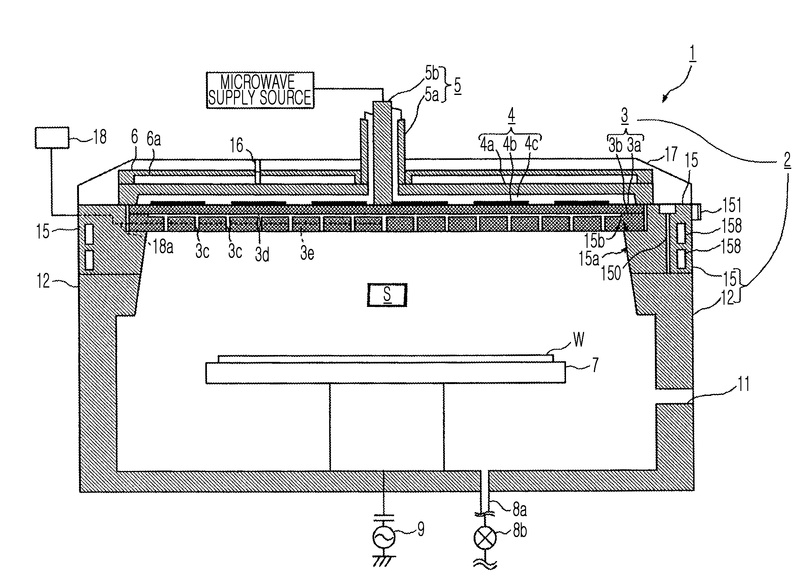
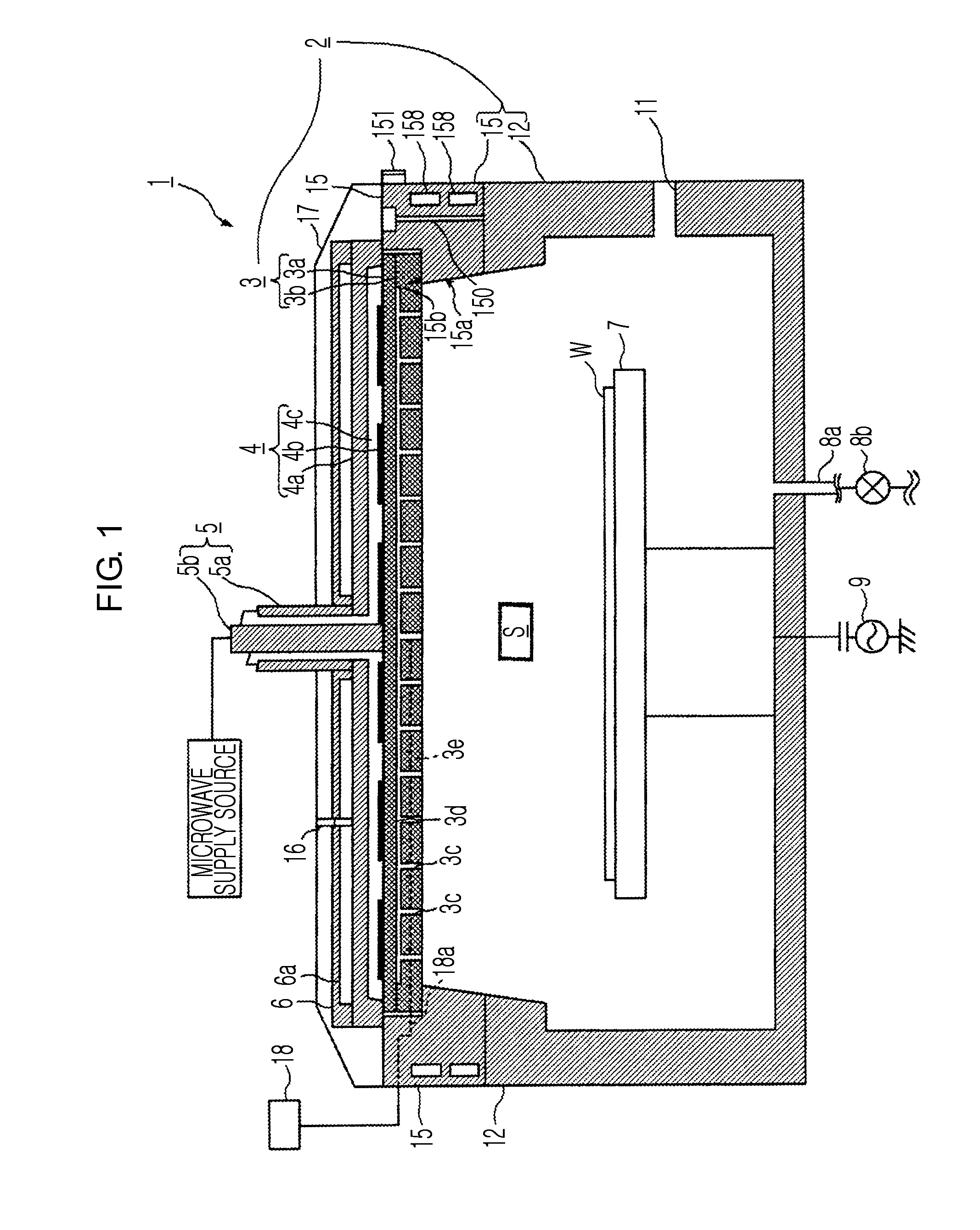
[0024]By using a plasma processing apparatus, a plasma processing method, and a mechanism for regulating a temperature of a dielectric window according to the present invention, a better plasma processing characteristic can be achieved by making it uniform a temperature distribution of the dielectric window used for plasma processing.

Problems solved by technology

Overheating of the dielectric window may cause undesirable results, for example, changing the efficiency in exciting process gas or decomposing the process gas.

Method used


Image

  • Plasma processing apparatus, plasma processing method, and mechanism for regulating temperature of dielectric window
  • Plasma processing apparatus, plasma processing method, and mechanism for regulating temperature of dielectric window
  • Plasma processing apparatus, plasma processing method, and mechanism for regulating temperature of dielectric window

Examples


embodiment

[0141]FIG. 9 shows characteristics of three types of heating devices (short-wavelength infrared ray, medium-wavelength infrared ray, and carbon (far infrared ray)). A cross-sectional size of a tube is expressed as the product of X and Y, in the case of the lamp heaters 151 of FIG. 4.

[0142]A temperature stability time is related to responsiveness. Since it is easier to control a temperature of a heating device having a shorter temperature stability time, the heating device having the shorter temperature stability time is more suitable. Since a heating device having a longer average lifespan needs a smaller number of exchanges and a shorter maintenance time, the heating device having the longer average lifespan is more preferable. Considering them, it is preferable that a heating means is a heating device using carbon as a heat source. However, since a heating device using carbon as a heat source is large, the heating device may not be suitable for the plasma processing apparatus 1. I...


PUM

PropertyMeasurementUnit
Temperatureaaaaaaaaaa
Flow rateaaaaaaaaaa
Distributionaaaaaaaaaa

Abstract

Provided are a plasma processing apparatus, a plasma processing method, and a mechanism for regulating a temperature of a dielectric window, which can achieve a better plasma processing characteristic by more precisely controlling the temperature of the dielectric window through which a microwave used for plasma processing is transmitted. The plasma processing apparatus is provided with a processing container, a dielectric window (shower plate), an antenna, a waveguide, a cooling block, a substrate holder, and a holding ring (upper plate) attached to the upper portion of the processing container. A circumferential portion of the dielectric window is engaged with the holding ring. The cooling block provided with a cooling flow path through which a heat medium can flow is provided on the antenna. A temperature sensor is provided around the waveguide, and a temperature of the antenna or the like is detected. A lamp heater is provided in an inside of the holding ring. The dielectric window is controlled to have a predetermined temperature distribution, by a cooling means of the cooling block and a heating means of the holding ring which are controlled by a control means.

Description

TECHNICAL FIELD[0001]The present invention relates to a plasma processing apparatus, a plasma processing method, and a mechanism for regulating a temperature of a dielectric window.BACKGROUND ART[0002]In a semiconductor manufacturing process, plasma processing is widely performed for the purpose of thin film deposition, etching, or the like. In order to obtain a semiconductor with high performance and high function, uniform plasma processing is required to be performed on an entire surface to be processed of a substrate to be processed in a space with a high degree of cleanness. Such a requirement is further increased as substrates get larger.[0003]At present, a method of exciting a process gas by using a microwave is widely used as a method for generating plasma in plasma processing. A microwave has the property of being transmitted through a dielectric. A microwave can be irradiated into a plasma processing apparatus by providing a window (hereinafter, referred to as a dielectric ...

Claims


Application Information

Patent Timeline
IPC IPC(8): C23F1/00C23F1/08C23C16/455C23C16/511C23C16/52
CPCH01J37/32192H01J37/32522H01J37/32238H05H1/46
Inventor NISHIMOTO, SHINYA
Owner TOKYO ELECTRON LTD
Why Eureka
Eureka Blog
Learn More