Hermetic Compressor

a compressor and hermetic technology, applied in the direction of positive displacement liquid engines, piston pumps, liquid fuel engines, etc., can solve the problems of increasing components, reducing thermal efficiency, unsatisfactory lubrication, etc., and achieves simple structure, reduced costs, and simplified upper structure.

Inactive Publication Date: 2011-07-07
SANDEN CORP
View PDF11 Cites 2 Cited by
  • Summary
  • Abstract
  • Description
  • Claims
  • Application Information

AI Technical Summary

Benefits of technology

In the hermetic compressor recited in claim 1, the refrigerant with the lubricating oil is conveyed to the stator through the discharge passage extending at least either through the compression unit and the primary shaft frame, or between the inner wall surface of the body and the compression unit and primary shaft frame, and the refrigerant is discharged from the hermetic container through the discharge pipe fitted at the body of the hermetic container. Thus, the hermetic compressor does not require a device (discharge head) provided above the compression unit to guide the lubricant oil and refrigerant toward the oil holding chamber at the bottom of the hermetic container, thereby preventing them from flowing directly into the discharge pipe. The hermetic container can therefore have a simplified upper structure, resulting in a reduction in costs.
The refrigerant with the lubricating oil passes through not only the oil separation plate but also the stator having coils. This ensures that the lubricating oil is separated from the refrigerant so that only the refrigerant is satisfactorily discharged from the hermetic container.
In the hermetic compressor recited in claim 2, the discharge passage is provided in the form of a pipe. Thus, with a simple structure, the refrigerant with the lubricating oil is reliably guided toward the stator of the electric motor.
In the hermetic compressor recited in claim 3, the discharge passage includes a hole extending through the compression unit and the primary shaft frame. This enables the refrigerant with the lubricating oil to be reliably guided toward the stator of the electric motor with a simpler structure, and also enables a reduction in costs.
In the hermetic compressor recited in claim 4, the discharge pipe is in a position opposite to the wires connected to the electric motor, with the rotary shaft between. This allows the refrigerant to be smoothly and efficiently discharged from the hermetic container, minimizing its interference with the wires connected to the electric motor.

Problems solved by technology

If a large amount of the lubricating oil is discharged with the refrigerant through a discharge hole after serving as a lubricant and a sealant in relevant parts inside the container, it leads to problems, such as unsatisfactory lubrication and a reduction in thermal efficiency.
This results in an increase in components, and the hermetic compressor is likely to have a complicated structure.

Method used


Image

  • Hermetic Compressor
  • Hermetic Compressor
  • Hermetic Compressor

Examples


embodiment

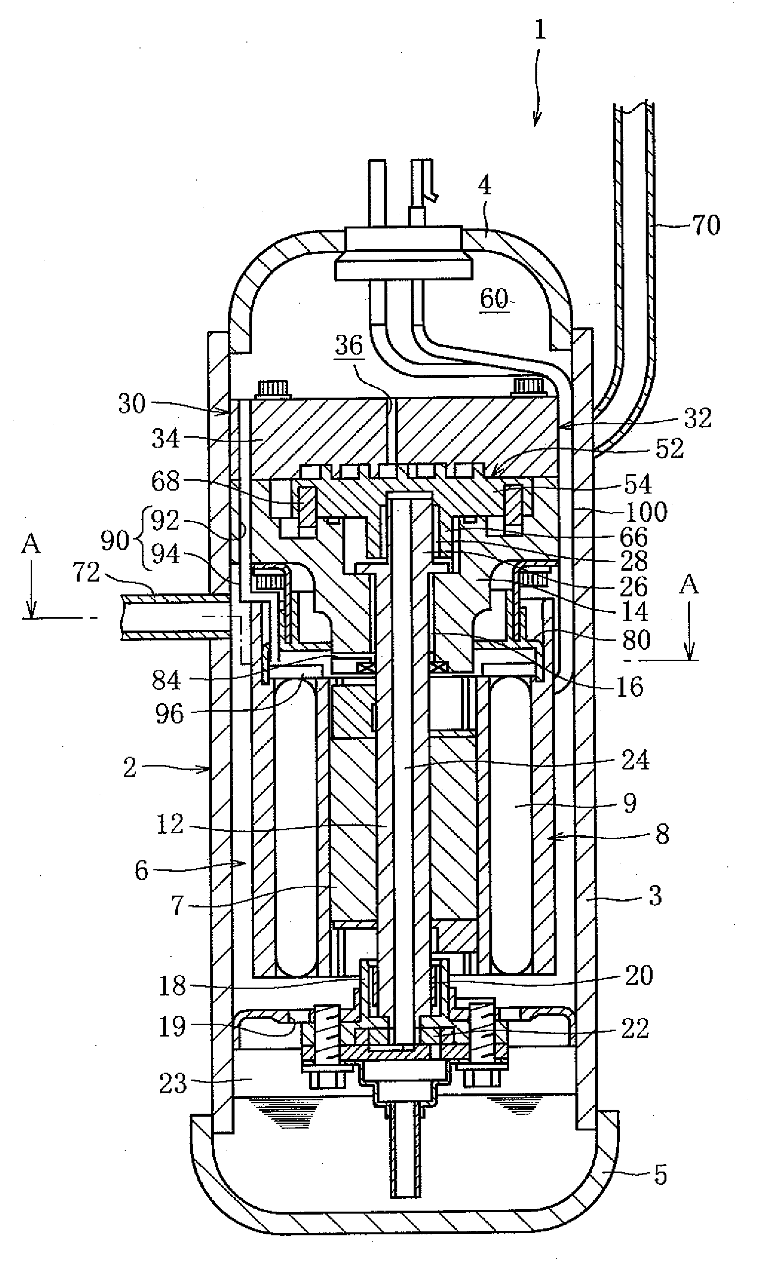
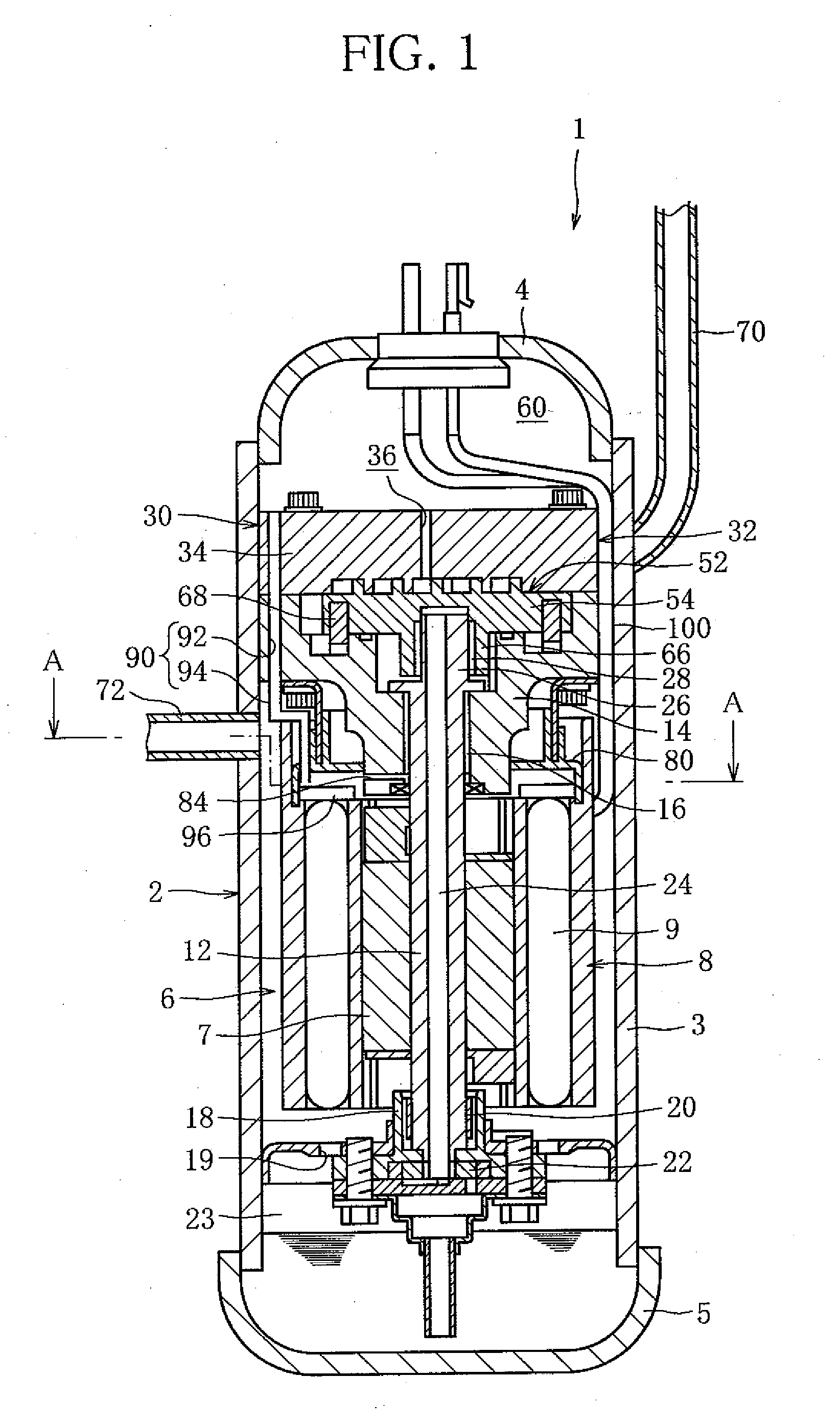
FIG. 1 is a vertical cross-sectional view of a hermetic compressor according to the present invention. The compressor 1 is a scroll compressor and incorporated in a refrigeration circuit of a refrigeration system, a heat pump water heater or the like. The circuit provides a path along which carbon dioxide refrigerant (hereinafter referred to simply as “refrigerant”), which is an example of a working fluid, circulates. The compressor 1 sucks in and compresses the refrigerant, thereby forcing it to circulate along the path.

The compressor 1 has a housing (hermetic container) 2. A body 3 of the housing 2 is hermetically sealed with upper and lower covers 4, 5 hermetically fitted in the body 3 at the top and bottom thereof, respectively. The interior of the body is at high discharge pressure.

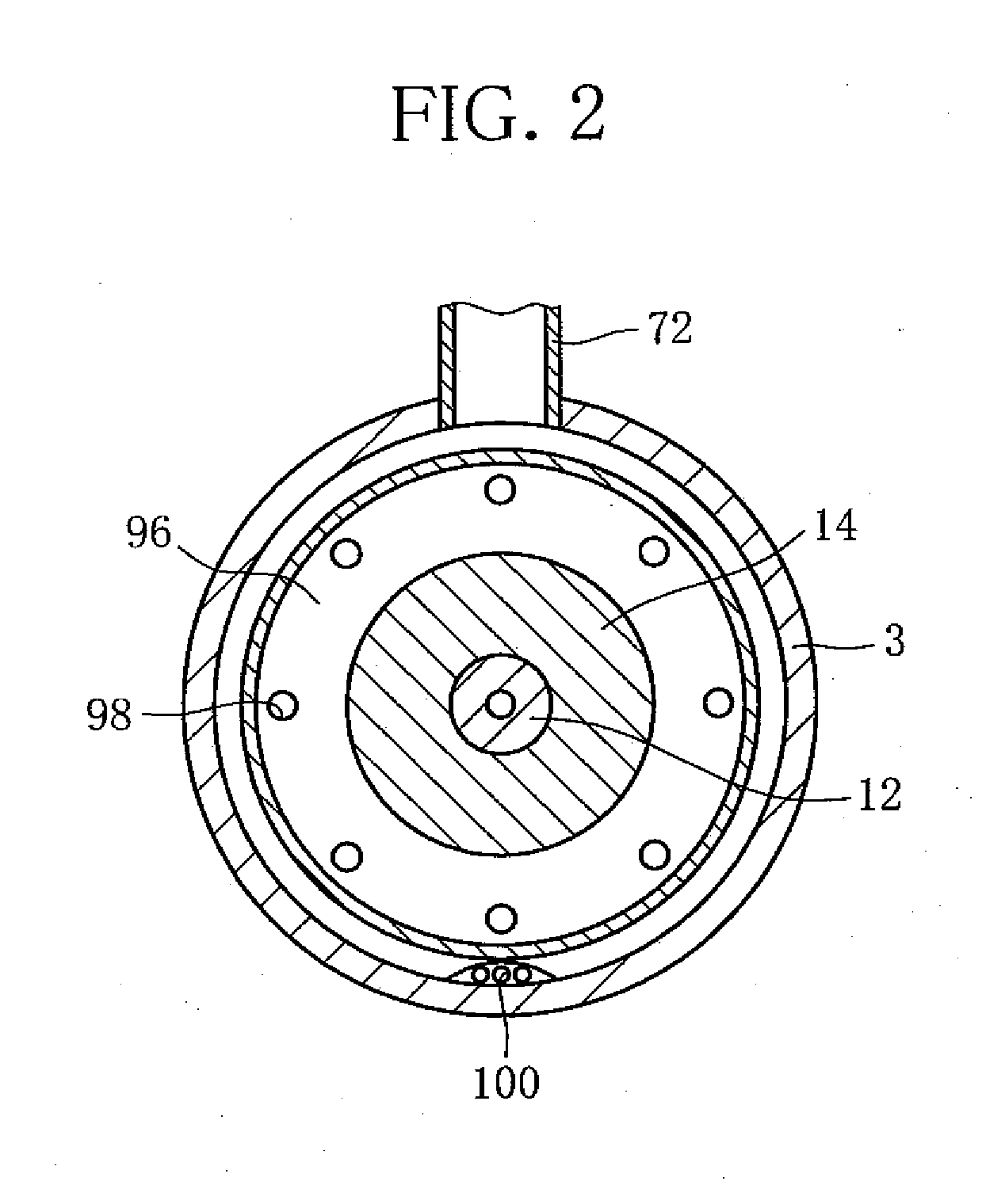
An electric motor (electromotor, hereinafter referred to simply as “motor”) 6 is disposed inside the body 3, and a rotary shaft 12 is disposed inside the motor 6. Specifically, the motor 6 includes a...


PUM


Abstract

There is provided a hermetic compressor which has a simplified structure and can satisfactorily separate a lubricating oil from a refrigerant and efficiently discharge the refrigerant from a hermetic container. A discharge passage (90) is provided to extend through a scroll unit (30) and a primary shaft frame (14), or between an inner wall surface of a body (3) of a hermetic container (2) and the scroll unit (30) and primary shaft frame (14) to guide the refrigerant with the lubricating oil directly to a stator (8) of an electric motor (6). Over the stator (96), an oil separation plate (96) is provided to separate the lubricating oil from the refrigerant conveyed through the discharge passage (96). A discharge pipe (72) is fitted to the body, below the primary shaft frame, to allow the refrigerant with the lubricating oil removed to be discharged from the hermetic container.

Description

TECHNICAL FIELDThis invention relates to a hermetic compressor, specifically a discharge passage for a refrigerant and a lubricating oil.BACKGROUND ARTA hermetic compressor of a type to which the present invention relates comprises a scroll unit arranged inside a hermetic container to perform a process of sucking in, compressing and discharging a refrigerant, and supplies a lubricating oil to the scroll unit and a scroll-unit driving part. The lubricating oil not only lubricates sliding surfaces of the scroll unit, bearings, etc., but also seals the sliding surfaces. The lubricating oil is held in an oil holding chamber at the bottom of the hermetic container and circulates inside the hermetic container, temporarily mixing with the refrigerant.If a large amount of the lubricating oil is discharged with the refrigerant through a discharge hole after serving as a lubricant and a sealant in relevant parts inside the container, it leads to problems, such as unsatisfactory lubrication an...

Claims


Application Information

Patent Timeline
Patent Type & Authority Applications(United States)
IPC IPC(8): F04B35/04
CPCF04C18/0215F04C2240/806F04C29/026F04C23/008
Inventor KOBAYASHI, NORIYUKI
Owner SANDEN CORP
Why Eureka
Try Eureka