Liquid-phase gas collection

a technology of liquid phase and gas collection, applied in the field can solve the problems of reducing the efficiency of liquid phase gas collection so as to achieve the effect of reducing the risk of contamination

Inactive Publication Date: 2011-06-30
ENDESA GENERACION
View PDF5 Cites 3 Cited by
  • Summary
  • Abstract
  • Description
  • Claims
  • Application Information

AI Technical Summary

Benefits of technology

[0031]Unlike the existing CO2-fixation processes that use microalgae or cyanobacteria found in the state of the art, in the process of the invention, the CO2 is supplied to the reactor previously dissolved in the aqueous phase, in the different water-soluble carbonated forms (CO2, H2CO3, HCO3−, CO3═), for which reason the transport efficiency is 100%. As regards the photosynthetic organisms that may be used, preferably, without being limited thereto, both cyanobacteria (Bacteria; Cyanobacteria) and green algae...

Problems solved by technology

The increase in the emission of pollutant gases, mostly generated by combustion processes, particularly of fossil fuels (coal, oil, natural gas), may lead to an overheating of the earth's surface (greenhouse effect).
This represents an economic and environmental problem for developed countries, but especially for developing countries, whose high level of CO2 emissions may entail significant sanctions at the international level, thereby delaying their incorporation into First-World countries.
However, this transformation process from inorganic to organic carbon, which occurs naturally, is very slow.
The disadvantages are that they require a temperature increase in the desorption phase (50° C.-100° C.
The disadvantage is that as yet they have not been used at the scale and under the conditions, in terms of availability and cost, which are necessary for CO2 capture systems (and the CO2 recovery phase).
The disadvantage is that as yet it has not been used at the scale and under the conditions, in terms of availability and cost, which are necessary for CO2 capture systems in large emission foci.
Additives are habitually used to increase the absorption capacity of K2CO3 solutions, and they have the disadvantage of a ...

Method used


Image

  • Liquid-phase gas collection
  • Liquid-phase gas collection
  • Liquid-phase gas collection

Examples


example

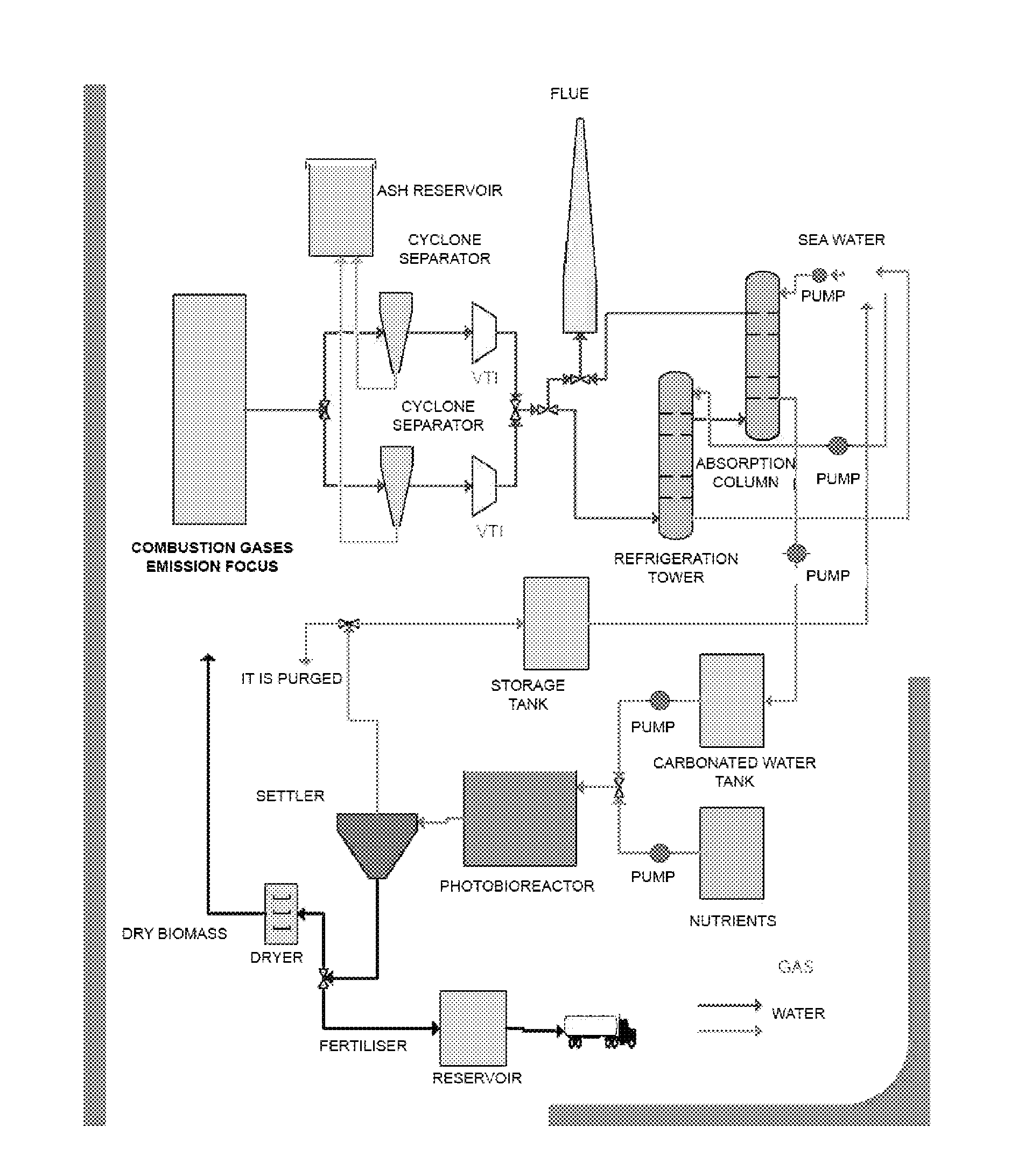
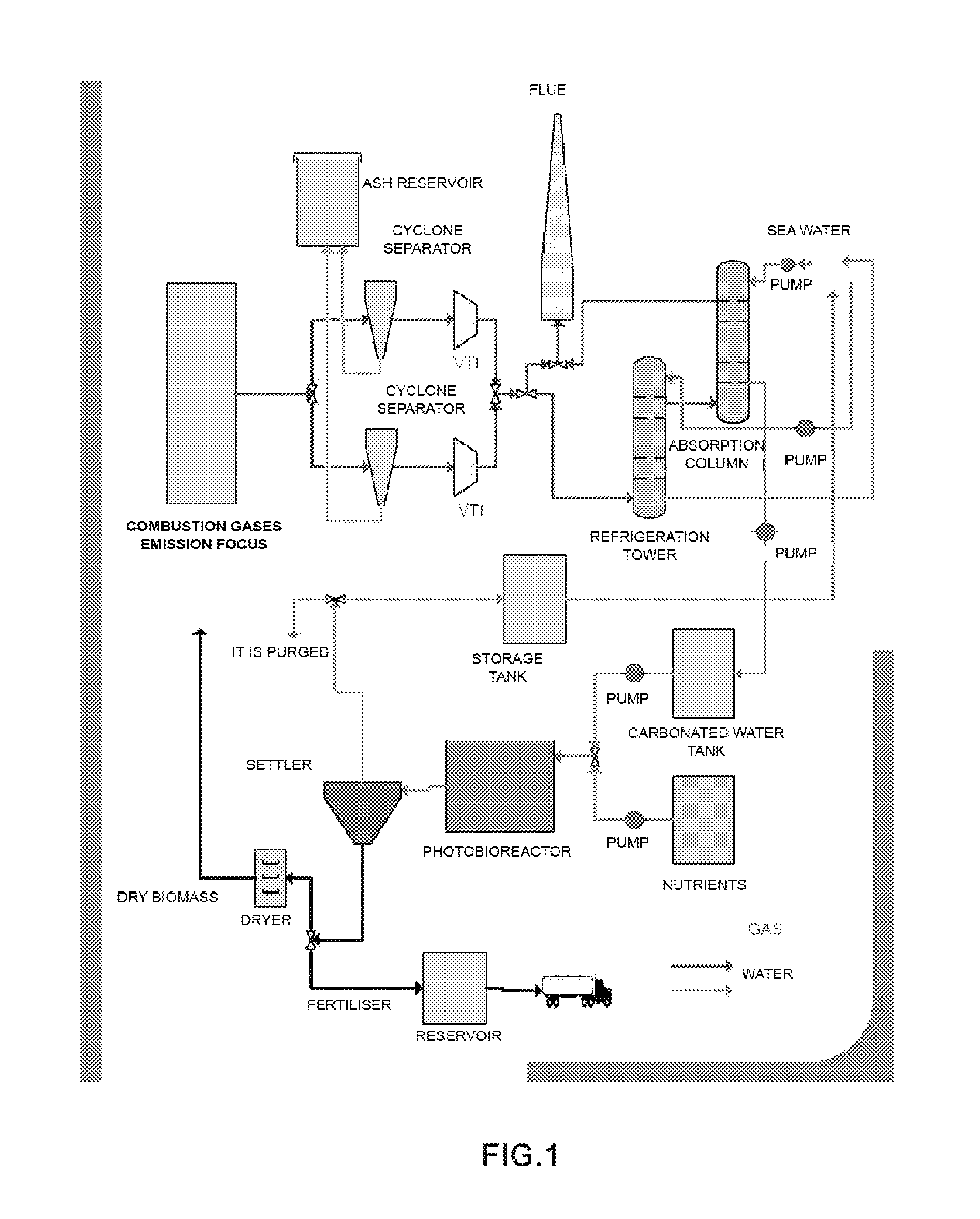
[0047]In this example, the inventors have designed a demonstration plant that makes it possible to assay the process of the invention, with a 250-l fluidisation column, for the purification of gases from a gas-oil boiler.

CO2 Capture System

[0048]The capture of CO2 was performed in a 250-l fluidisation column, humidifying the gas stream with the liquid phase. The system bears inundation flow rates of 20 l / min of liquid and 350 l / min of gases, the minimum flow rate to wet the column being 4 l / min of liquid (experimental data).

[0049]The liquid phase was prepared by adding about 11 g / l of NaHCO3 and 22 g / l of Na2CO3, reaching a pH of 10. The total concentration of inorganic carbon was 4.0 g / l.

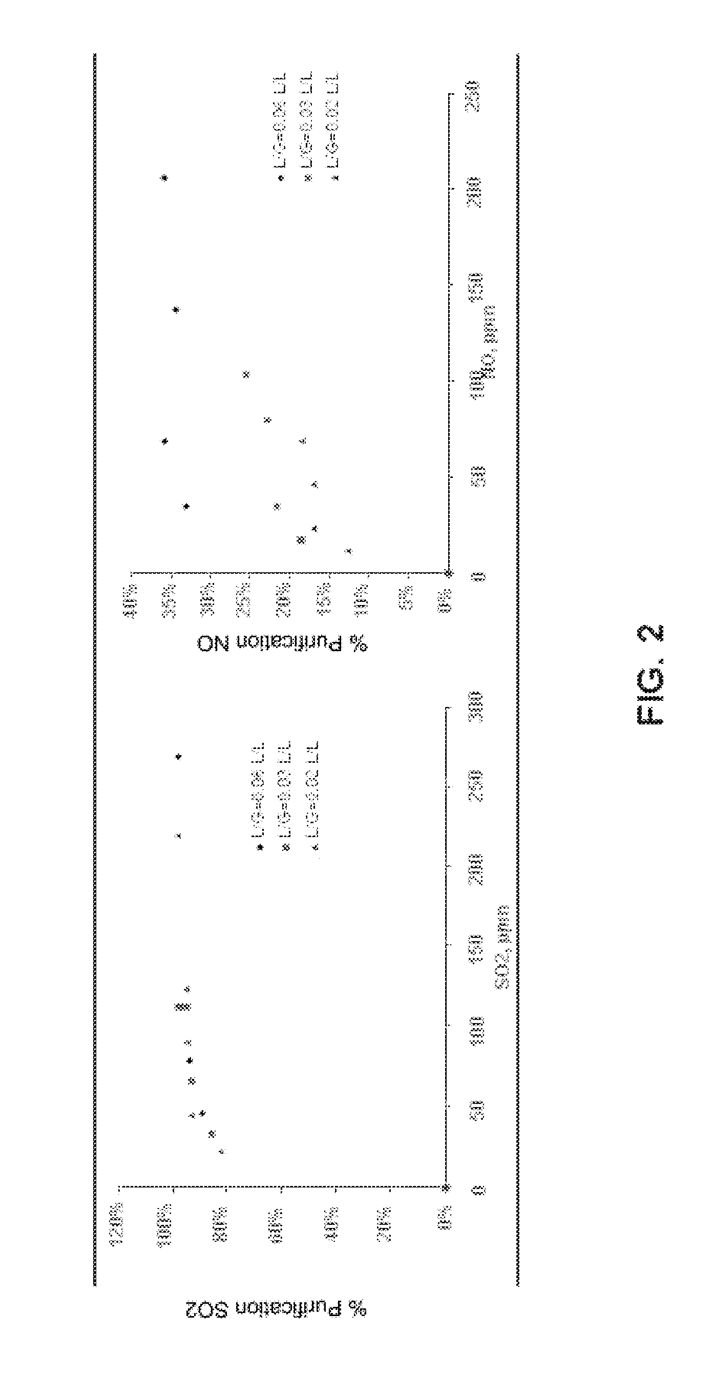
[0050]Under these conditions, a CO2 purification efficiency of 80% may be achieved, as well as purification efficiencies of 50% and 95% for NOx and SOx, respectively.

[0051]Operating with this column, with 10% binary air-CO2 mixtures as the gas phase and water from the mains as the liquid phase, the ...


PUM

PropertyMeasurementUnit
Concentrationaaaaaaaaaa

Abstract

A method for collecting combustion gases by (a) contacting a liquid phase with a gas flow containing said gases, where the liquid phase contains carbonate/bicarbonate buffer salts in a ratio of around 2:1, with a total inorganic carbon concentration no higher than 25 g/L and pH values between 8 and 12; and (b) recovering the CO2-rich liquid phase produced in step (a).

Description

[0001]This invention falls within the field of chemistry, chemical engineering and the environment. It relates to a gas capture process in the liquid phase, and the subsequent recovery of this phase, by coupling the process to a biological system.PRIOR STATE OF THE ART[0002]The increase in the emission of pollutant gases, mostly generated by combustion processes, particularly of fossil fuels (coal, oil, natural gas), may lead to an overheating of the earth's surface (greenhouse effect). This represents an economic and environmental problem for developed countries, but especially for developing countries, whose high level of CO2 emissions may entail significant sanctions at the international level, thereby delaying their incorporation into First-World countries.[0003]The solution may be addressed either by developing new, less polluting technologies, or by developing systems and processes capable of capturing those gas emissions and, if possible, reconverting them. CO2, which is the ...

Claims


Application Information

Patent Timeline
IPC IPC(8): B01D53/62
CPCB01D53/62B01D53/77B01D53/96B01D2251/304B01D2251/606Y02C10/06B01D2257/504C12F3/02C12N1/12Y02C10/04B01D2257/302Y02C20/40B01D53/1462B01D53/1493B01D53/34
Inventor ACIEN FERNANDEZ, FRANCISCO GABRIELMOLINA GRIMA, EMILIOFERNANDEZ SEVILLA, JOSE MARIAGONZALEZ LOPEZ, CYNTHIA VICTORIALLAMAS MOYA, BERNARDOBALLESTEROS APARICIO, JUAN CARLOS
Owner ENDESA GENERACION
Why Eureka
Try Eureka