
Method for the manufacture of a fiber-reinforced component, device for implementing the method, and fiber-reinforced component

a fiber-reinforced component and manufacturing method technology, applied in the direction of turning machine accessories, drawing profiling tools, domestic articles, etc., can solve the problems of increased labor intensity, increased cost, and difficulty in processing fiber-reinforced duroplastic plastics, and achieve the effect of simple and easy automation

Active Publication Date: 2011-06-30
AIRBUS OPERATIONS GMBH
View PDF8 Cites 18 Cited by
  • Summary
  • Abstract
  • Description
  • Claims
  • Application Information

AI Technical Summary

Benefits of technology

[0010]An aspect of the present invention provides a simplified and easily automatable method for the manufacture of, in particular, fiber-reinforced thermoplastic plastic components in great numbers, which components after completion of the forming process already comprise integral edge sealing, at least in some sections, and which components are at the same time directly dimensionally accurate so that no further mechanical reworking steps are needed any longer in order to achieve the specified geometry and / or in order to create the edge seal.
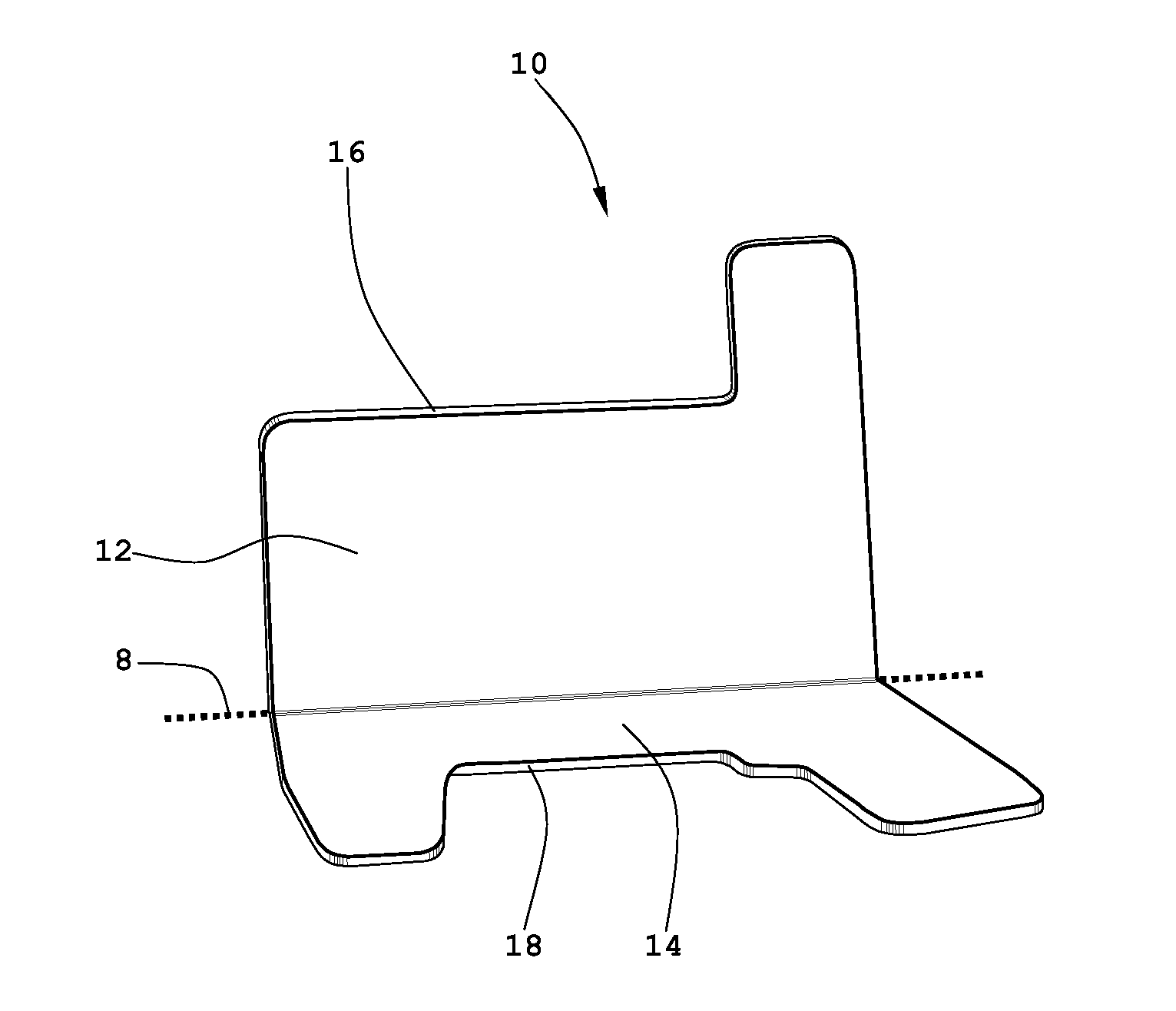
[0016]To this effect the blank that has been formed so that it becomes the finished component has from the very beginning been given an integral thermoplastic edge seal, free of any carbon fibers, which edge seal prevents contact corrosion, and is at the same time dimensionally accurate so that further mechanical reworking steps are no longer required. Moreover, the sharp edges, which otherwise arise in the edge region of the component as a result of interlaminar gliding during the forming process, are blunted, i.e. made safe, so that the component can be handled without any danger of injury. Forming primarily takes place under the effect of high pressing pressure that is generated by the moulding tool and that is acting on the already heated blank. The tool temperature is to be selected such that a specified cooling rate is maintained.
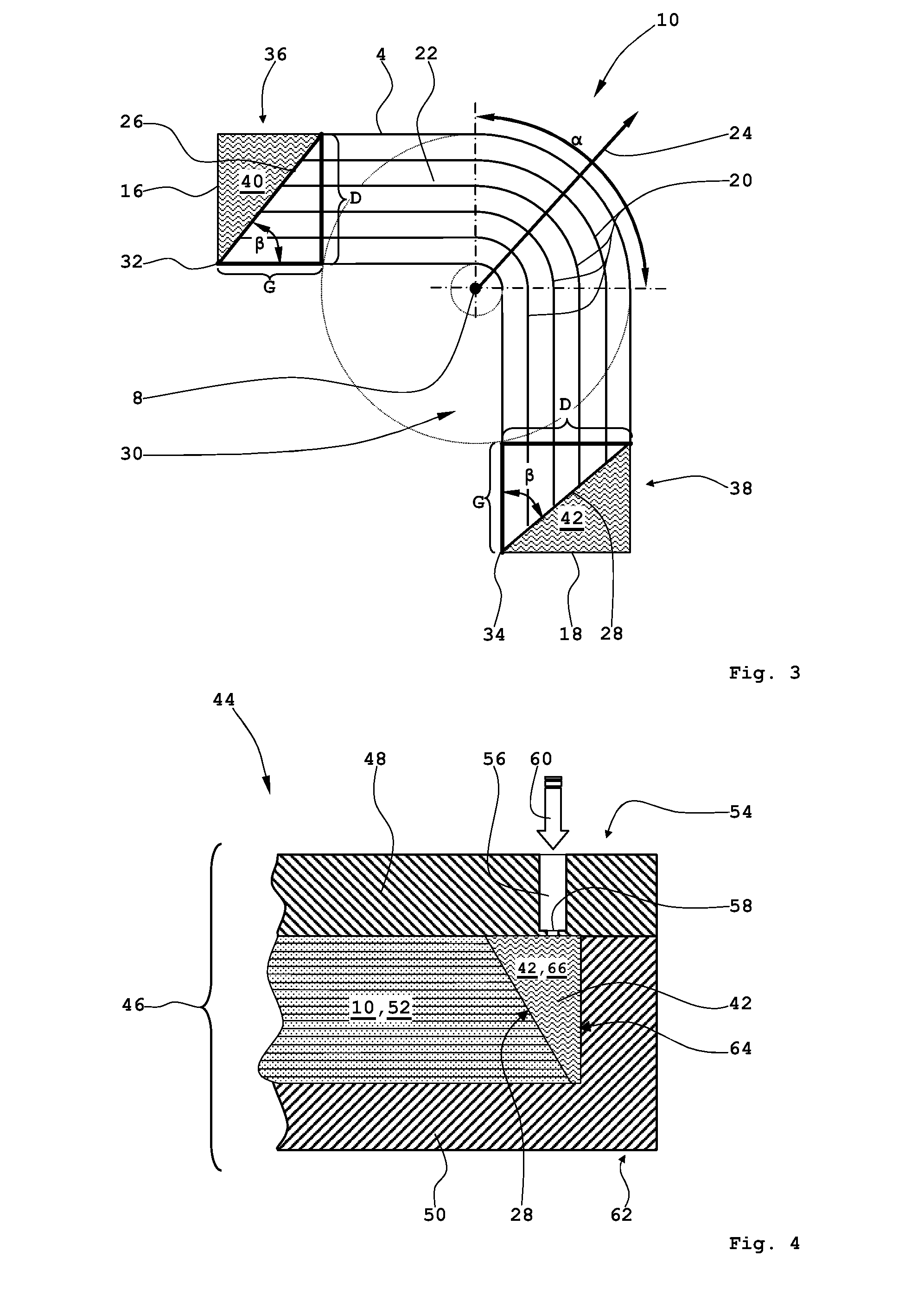
[0022]This approach ensures very good dimensional accuracy of the separated contour while at the same time ensuring high processing speeds. Furthermore, in particular, water jet cutting provides an advantage in that the blank can be cut from the semifinished product by means of a water jet that is inclined relative to the top so that the cut edges extend at least in some sections at an angle of inclination of less than 90° relative to horizontal. The angle of inclination can be selected such that, after the process of forming the blank, component edges that are at a right angle in relation to the component top and to the component bottom of the finished component are automatically obtained.
[0024]In this way it is possible already during the forming process to provide integral edge sealing so as to prevent contact corrosion. Furthermore, the device makes possible a forming process of the blank, which has been heated to above melting temperature in an upstream oven, which forming process results in directly dimensionally accurate fiber-reinforced components that generally speaking do not require any further subsequent treatment. The device also makes it possible to manufacture fiber-reinforced components in large numbers.
[0030]As a result of this, injection of the thermoplastic plastic material takes place in the region of the void, which region has the widest opening. Depending on the geometric shape of the cavity and / or its spatial position relative to the moulding tool, in a manner that differs from the aforesaid it may be advantageous to integrate the nozzles in the bottom tool or in both tool parts.

Problems solved by technology

Processing the fiber-reinforced duroplastic plastics is often involved and expensive because large-format heatable moulds or autoclaves with vacuum bags are required in order to be able to cure components with the application of pressure and / or temperature to form finished components that are true to shape.
Furthermore, the introduction of the reinforcement fibers, in particular their alignment so that it takes into account the flow of force, prior to the impregnation process causes additional difficulties.
Moreover, the production of large numbers of carbon-fiber-reinforced duroplastic components while at the same time ensuring good and reliable reproducibility of the geometric and mechanical specifications can be achieved only at significant expense.
In recent times fiber-reinforced thermoplastic materials have promised a remedy to the aforesaid, which fiber-reinforced thermoplastic materials can be manufactured with justifiable expenditure in large numbers with constantly good dimensional accuracy, albeit with slightly inferior mechanical properties.

Method used


Image

  • Method for the manufacture of a fiber-reinforced component, device for implementing the method, and fiber-reinforced component
  • Method for the manufacture of a fiber-reinforced component, device for implementing the method, and fiber-reinforced component
  • Method for the manufacture of a fiber-reinforced component, device for implementing the method, and fiber-reinforced component

Examples


Embodiment Construction

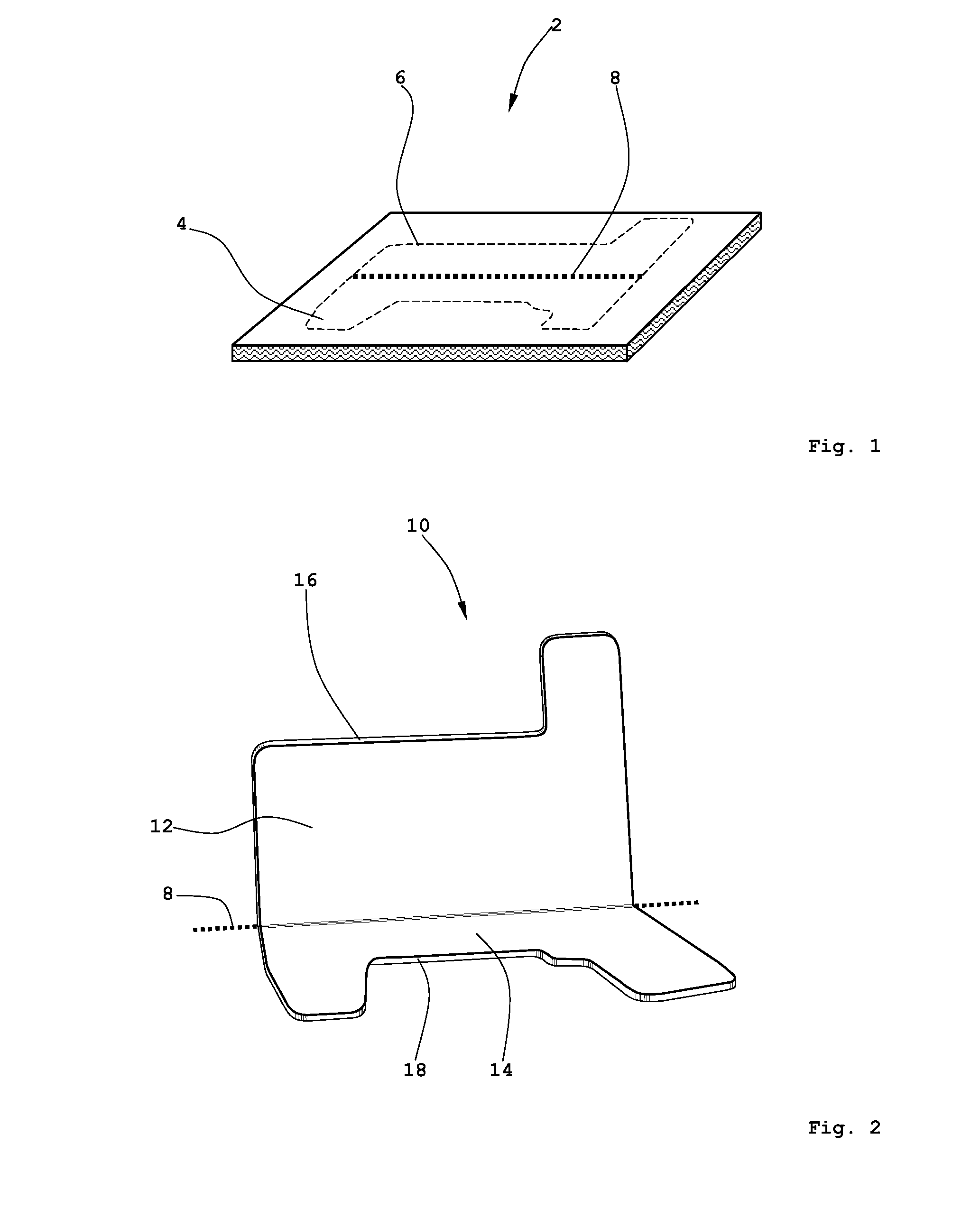
[0041]FIG. 1 shows a plate-shaped semifinished product that preferably comprises a carbon fiber-reinforced thermoplastic plastic material.

[0042]A likewise plate-shaped semifinished product 2 comprises a thermoplastic matrix in which reinforcement fibers, for example carbon fibers, are embedded. The thermoplastic matrix can, for example, comprise a polyphenylenesulfide (PPS) polyetheretherketone (PEEK), polyetherimide (PEI) polyetherketoneketone (PEKK) or polyethylenenterephthalate (PET) or some other high-performance plastics. In order to exclude any surface corrosion effects, apart from possible contact corrosion in the component edge region, also in the region of the top and bottom (not shown with reference characters) of the formed component, in each case below the top or below the bottom layers of reinforcement fibers, which comprise glass fibers, can be embedded in the thermoplastic matrix of the semifinished product 2 as the last or final layers.

[0043]From a middle region (not...


PUM

PropertyMeasurementUnit
Pressureaaaaaaaaaa
Angleaaaaaaaaaa
Shapeaaaaaaaaaa

Abstract

A method for the manufacture of a fiber-reinforced component includes heating a blank of a carbon-fiber-reinforced thermoplastic plastic material to at least a melting temperature of the thermoplastic plastic material; introducing the blank into an at least two-part moulding tool; forming the fiber-reinforced component by applying pressure on the blank using the moulding tool; and injecting a further thermoplastic plastic material into at least one edge region of the moulding tool so as to form an edge seal.

Description

CROSS REFERENCE TO PRIOR APPLICATIONS[0001]Priority is claimed to German Application No. DE 10 2009 060 689.0, filed Dec. 29, 2009 and to U.S. Provisional Application No. 61 / 290,520, filed Dec. 29, 2009. The entire disclosure of both applications is incorporated by reference herein.FIELD[0002]The invention relates to a method for the manufacture of a fiber-reinforced component, in particular of a connecting angle formed with a carbon-fiber-reinforced thermoplastic plastic material for the connection of frame elements to an exterior skin of a fuselage cell of an aircraft.[0003]The invention moreover relates to a device for the manufacture of a fiber-reinforced component, in particular of a connecting angle formed with a carbon-fiber-reinforced thermoplastic plastic material, with an at least two-part moulding tool for forming a plate-shaped tailored blank so that it becomes the component.[0004]Furthermore, the invention relates to a fiber-reinforced component, in particular manufactu...

Claims


Application Information

Patent Timeline
IPC IPC(8): B64C1/12B29C45/14B32B3/02
CPCB29C45/14221B29C45/14786B29C2045/14237B29K2105/12B29L2031/3082Y10T428/24777B64C2001/0072Y02T50/433B29C70/46Y10T428/24488B64C1/12Y02T50/40
Inventor BAKKER, PATRICKBRUEGGEMANN, FRANKEDELMANN, KLAUSHOPPE, GUENTER
Owner AIRBUS OPERATIONS GMBH
Learn More