
Integration of a Surface Heat Exchanger to the Wall of an Aerodynamic Flowpath by a Structure of Reinforcement Rods

a technology of surface heat exchanger and aerodynamic flow path, which is applied in the direction of engine cooling apparatus, stationary plate conduit assembly, air transportation, etc., can solve the problems of imposing rather substantial construction constraints, affecting the flow of the engine, and affecting the performance of the engin

Active Publication Date: 2011-06-23
TECHSPACE AERO
View PDF5 Cites 29 Cited by
  • Summary
  • Abstract
  • Description
  • Claims
  • Application Information

AI Technical Summary

Problems solved by technology

Various solutions are available to ensure the evacuation of the heat from such exchangers as, for example, the use of one or several scoops on the fairing which causes an increase of the drag, or the tapping of the engine airflow, which causes an aerodynamic disturbance of the flow of the engine, and, consequently, a decrease of performance.
According to a first embodiment, the oil flow channels are in the thickness of the wall forming the nose, which imposes rather substantial construction constraints.
This sandwich-type structure, despite being light and strong, has the drawback of having a limited thermal exchange capacity.
More generally, making this surface exchanger according to this teaching imposes particular constraints when making the wall of the separator nose.
The manufacturing cost of the walls is high and setting them in place is restrictive.
Furthermore, the thermal exchange capacity is limited due to the exchange surface, which is limited up to a certain distance downstream from the leading edge.
The extension of the exchange surface at a greater distance from the leading edge could cause mechanical stability problems due to the excess weight engendered by the exchanger.
Surface exchangers, although they optimize the aerodynamic impact, are generally more complex to manufacture and to integrate than the exchangers referred to as compact.
However, the major drawback of this arrangement is that the heat exchanger is subject to deterioration by outside objects which penetrate the turbojet engine.

Method used


Image

  • Integration of a Surface Heat Exchanger to the Wall of an Aerodynamic Flowpath by a Structure of Reinforcement Rods
  • Integration of a Surface Heat Exchanger to the Wall of an Aerodynamic Flowpath by a Structure of Reinforcement Rods
  • Integration of a Surface Heat Exchanger to the Wall of an Aerodynamic Flowpath by a Structure of Reinforcement Rods

Examples


Embodiment Construction

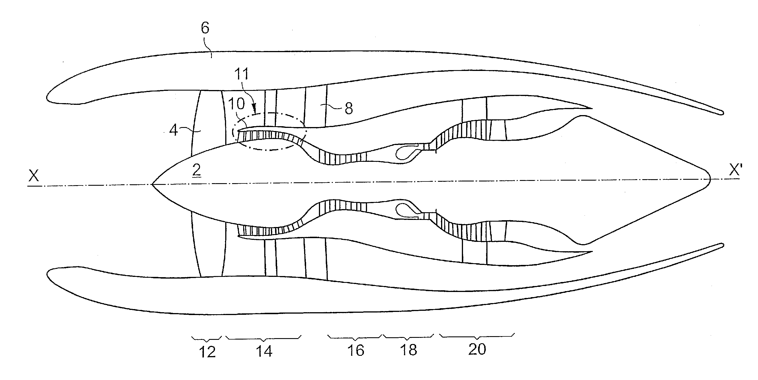
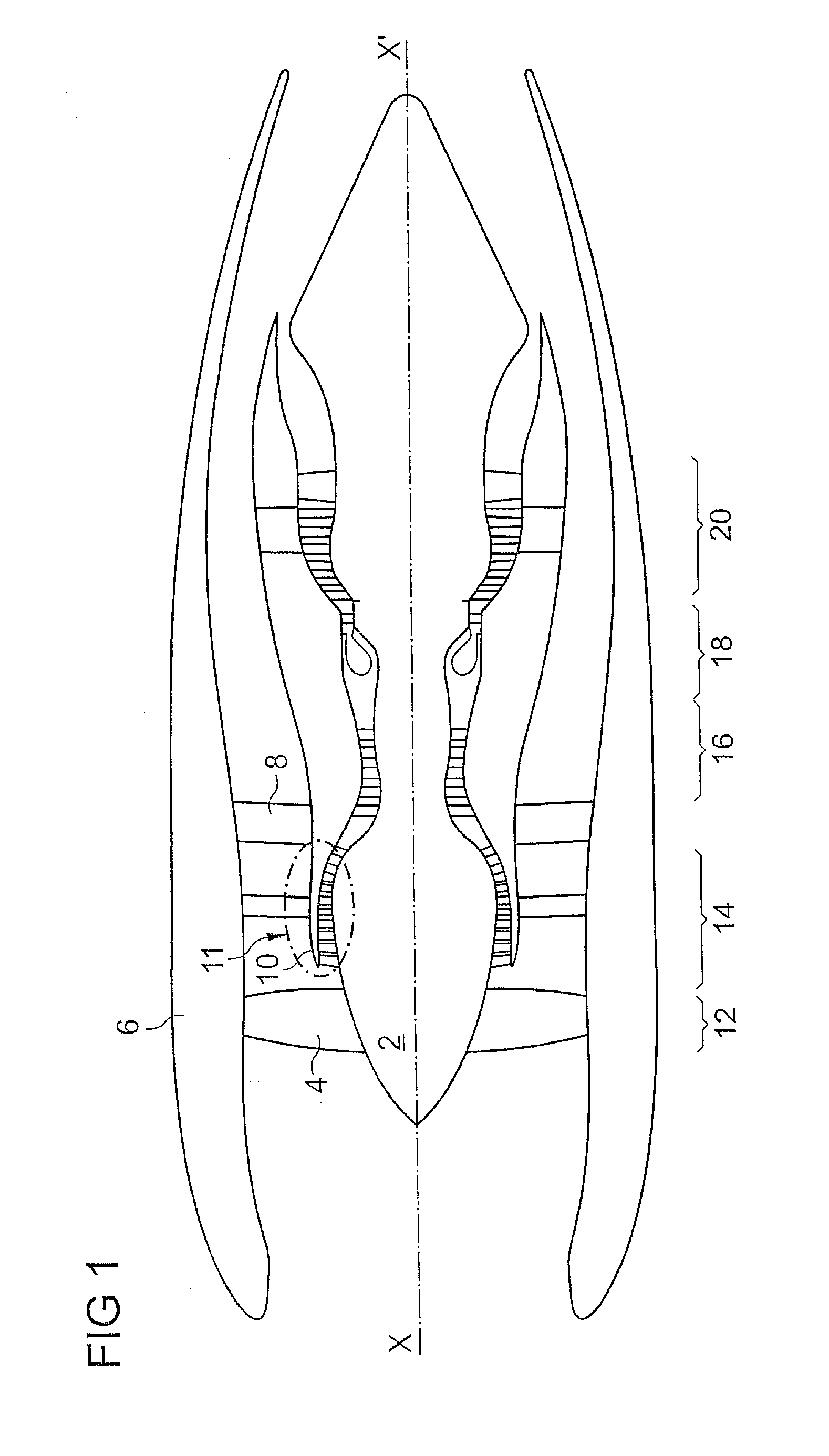
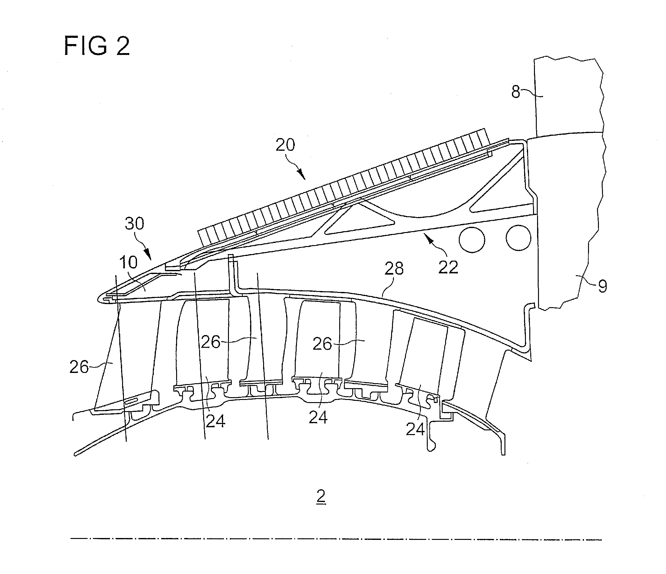
[0023]The present application discloses an integration of surface exchanger in a wall of the secondary flowpath enabling a substantial thermal exchange, while disturbing the secondary flow as little as possible, and which can be easily mounted.

[0024]The present application includes an inner annular wall or wall portion of the secondary flowpath of a bypass turbojet engine comprising a nose for separating primary and secondary flows and an intermediate casing, said wall or wall portion being situated between the leading edge of said separator nose and said intermediate casing; remarkable in that it comprises at least one surface air-oil heat exchanger forming an annular segment of said wall or wall portion; and at least one support arm of said wall or wall portion adapted to be fixed to the intermediate casing and extending from the intermediate casing toward said leading edge. These measures provide, among other things, the following advantages:[0025]a great cooling capacity since e...


PUM


Abstract

Setting in place of one or several coolers in the wall of a secondary flow of a bypass turbomachine. The wall extends from an intermediate casing toward a leading edge of a separator nose between a primary flow and the secondary flow. The wall includes a series of support arms attached to an intermediate casing, distributed over the perimeter of the wall and directed upstream. A series of surface air-oil heat exchangers forming wall segments are arranged end-to-end on the support arms, so as to form an annular wall. A shroud having a leading edge is arranged and fixed in the area of the upstream edges of the heat exchangers, so as to complete the wall. The support arms include hydraulic connectors connected to one another on each arm, adapted to cooperate with corresponding connectors in the area of the heat exchangers and in the area of the intermediate casing.

Description

[0001]This application claims priority under 35 U.S.C. §119 to European Patent Application No. 09180605.9, filed 23 Dec. 2009, which is incorporated herein by reference for all purposes.BACKGROUND[0002]1. Field of the Application[0003]The present application relates to the problem of cooling the lubrication circuit of a bypass turbomachine, more particularly to setting in place a cooler in the secondary flowpath of a bypass turbomachine for an optimized cooling of the lubrication circuit.[0004]2. Description of Related Art[0005]Various mechanical or electrical elements of a turbomachine must be lubricated and / or cooled, such as, for example, certain bearings, certain reducers, and the electrical equipment. To do so, a lubrication circuit is provided. The oil plays the role of a lubricant and also of a heat transfer fluid, which necessitates providing for the heat thus collected to be evacuated. Current turbojet engines generate more and more heat, particularly for the following reas...

Claims


Application Information

Patent Timeline
IPC IPC(8): F02K3/02F01D25/08F02C7/20
CPCF28F9/0075Y02T50/676F01D25/14F01D25/18F02C7/14F05D2260/232F02K3/02F05D2260/213F28D9/0018F28D2021/0089F28F3/048F02C7/18Y02T50/60
Inventor BAJUSZ, DENISDEPAEPE, DAVIDDERCLAYE, ALAINDUPUY, REGIS
Owner TECHSPACE AERO
Learn More