
Advanced catalysts for automotive applications

a technology for advanced catalysts and automotive applications, applied in the direction of physical/chemical process catalysts, metal/metal-oxide/metal-hydroxide catalysts, manufacturing tools, etc., can solve the problems of affecting the catalyst, the method of manufacturing the catalyst used in the catalytic converter suffers from a number of shortcomings, and the cost of platinum is extremely expensiv

Active Publication Date: 2011-06-16
UMICORE AG & CO KG +1
View PDF109 Cites 85 Cited by
  • Summary
  • Abstract
  • Description
  • Claims
  • Application Information

AI Technical Summary

Benefits of technology

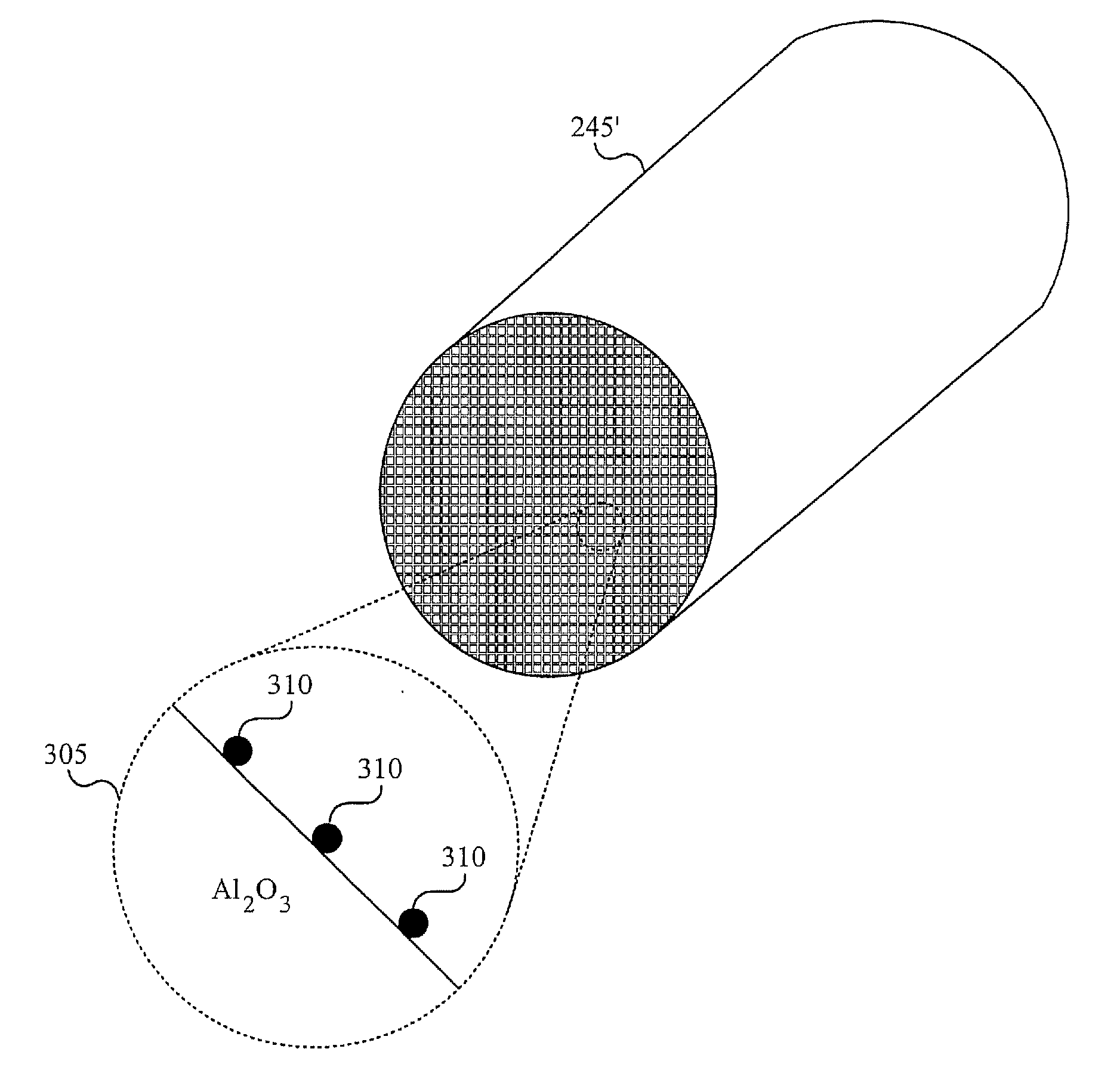
The patent describes a catalytic converter that includes nano-particles with active materials (such as platinum, palladium, or rhodium) on a support (such as alumina or alumina partially reduced with a surface layer). The nano-particles can be created using high temperature condensation technology and can be mixed with a carrier material (such as alumina) to create a dispersion. The dispersion can then be applied to a monolith and dried. The resulting catalytic converter has improved performance and can be used in a three-way or two-way catalytic converter. The technical effect of this invention is to provide a more effective and efficient catalytic converter with improved performance.

Problems solved by technology

However, these various methods of manufacturing the catalyst used in the catalytic converter suffer from a number of shortcomings.
It is understood that as the platinum particles become larger, it detrimentally affects the catalyst since surface area of the platinum atoms decreases.
In addition, since cost of platinum is extremely expensive, excessive use of platinum is unwanted.

Method used


Image

  • Advanced catalysts for automotive applications
  • Advanced catalysts for automotive applications
  • Advanced catalysts for automotive applications

Examples


Embodiment Construction

Reference will now be made in detail to implementations of the present invention as illustrated in the accompanying drawings. The drawings may not be to scale. The same reference indicators will be used throughout the drawings and the following detailed description to refer to identical or like elements. In the interest of clarity, not all of the routine features of the implementations described herein are shown and described. It will, of course, be appreciated that in the development of any such actual implementation, numerous implementation-specific decisions must be made in order to achieve the developer's specific goals, such as compliance with application, safety regulations and business related constraints, and that these specific goals will vary from one implementation to another and from one developer to another. Moreover, it will be appreciated that such a development effort will be a routine undertaking of engineering for those of ordinary skill in the art having the benef...


PUM

PropertyMeasurementUnit
dispersionaaaaaaaaaa
temperatureaaaaaaaaaa
structureaaaaaaaaaa

Abstract

Embodiments of present inventions are directed to an advanced catalyst. The advanced catalyst includes a honeycomb structure with an at least one nano-particle on the honeycomb structure. The advanced catalyst used in diesel engines is a two-way catalyst. The advanced catalyst used in gas engines is a three-way catalyst. In both the two-way catalyst and the three-way catalyst, the at least one nano-particle includes nano-active material and nano-support. The nano-support is typically alumina. In the two-way catalyst, the nano-active material is platinum. In the three-way catalyst, the nano-active material is platinum, palladium, rhodium, or an alloy. The alloy is of platinum, palladium, and rhodium.

Description

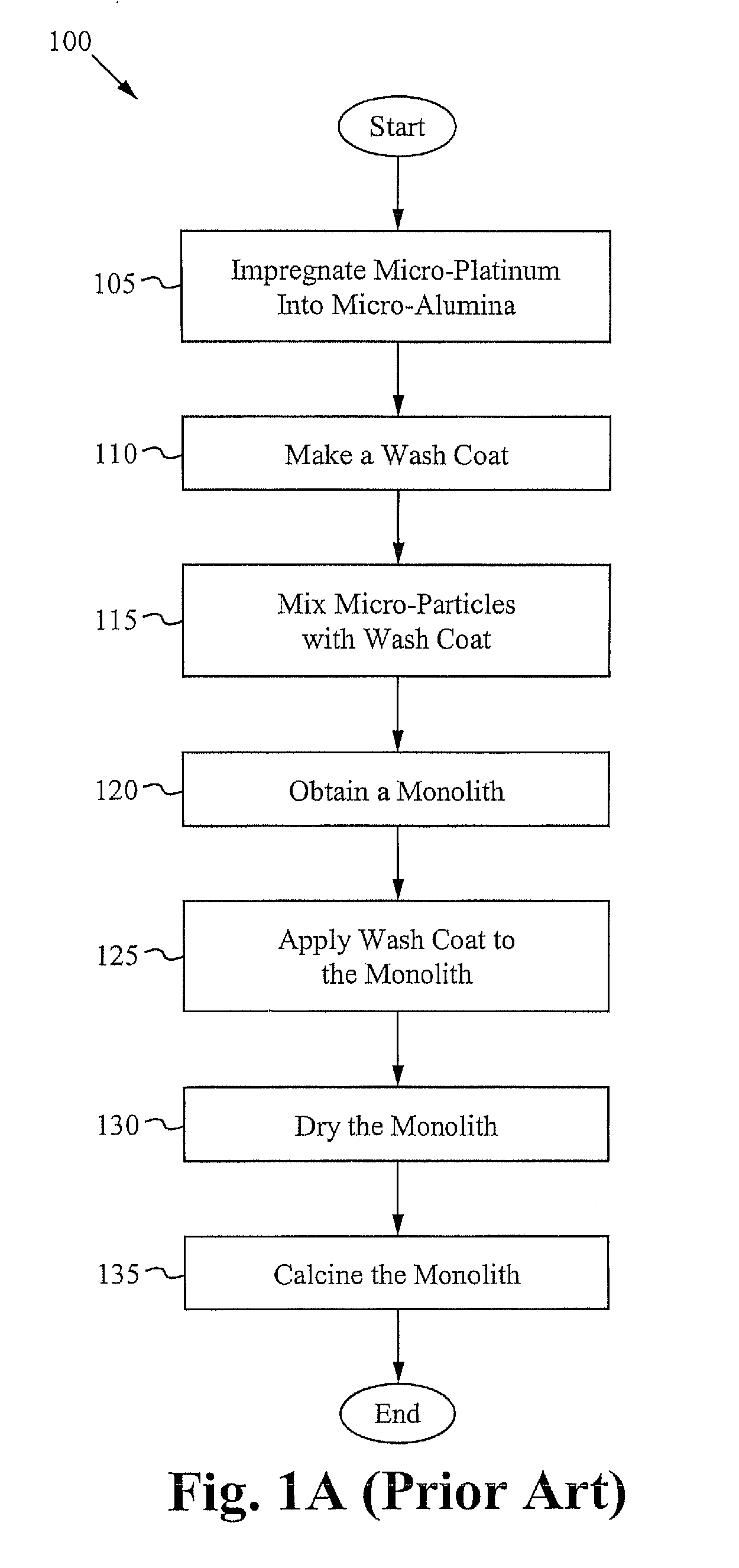
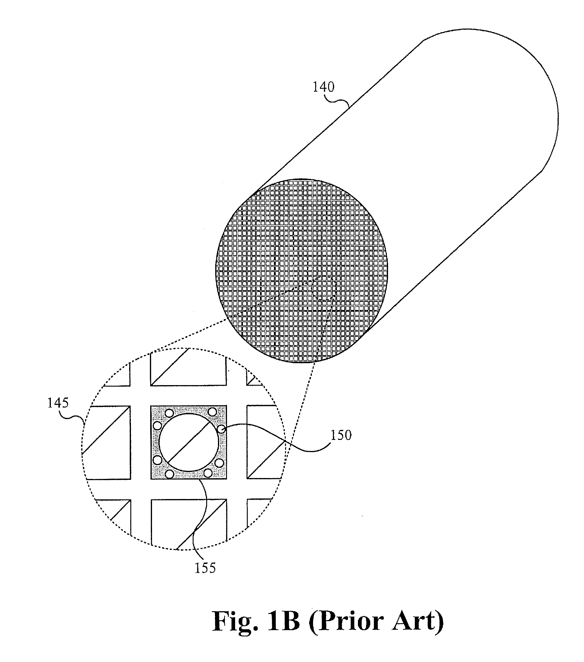
BACKGROUND OF THE INVENTIONA catalytic converter for a car uses a catalyst to convert, for example, three harmful compounds in car exhaust into less harmful compounds. The three harmful compounds include hydrocarbons in the form of unburned gasoline, carbon monoxide formed by the combustion of gasoline, and nitrogen oxide created when heat in the engine forces nitrogen in the air to combine with oxygen. There are two main structures used in catalytic convertershoneycomb and ceramic beads. Most automobiles today use the honeycomb structure. The honeycomb structure is housed in a muffler-like package that comes before the exhaust pipe. The catalyst helps to convert carbon monoxide into carbon dioxide, the hydrocarbons into carbon dioxide and water, and the nitrogen oxides back into nitrogen and oxygen.Various methods of manufacturing the catalyst used in the catalytic converter exist in the art. FIG. 1A illustrates a first conventional method of manufacturing the catalyst. The first ...

Claims


Application Information

Patent Timeline
Patent Type & Authority Applications(United States)
IPC IPC(8): B01J23/42B01J35/02B01J23/46B01J21/04B01J21/06B01J23/44B01J35/00B82Y30/00
CPCB01J23/42B01J37/0211B01J35/0013B01J37/00B01J37/32B01J37/349Y02T10/22B32B7/12B32B37/14B82Y30/00B82Y40/00C23C4/127B28B23/0087B01J37/009B01J23/8926B01J21/04B01J23/44B01J23/464B01J35/56C23C4/134Y02T10/12B01J35/23
Inventor YIN, QINGHUAQI, XIWANGBIBERGER, MAXIMILIAN A.
Owner UMICORE AG & CO KG
Learn More