
Lever connector

a technology of lever connector and lever body, which is applied in the direction of coupling device connection, coupling parts engagement/disengagement, incorrect coupling prevention, etc., can solve the problems of restricted engagement of the second housing in the inclined posture into the inside of the hood, and the inclined second housing will break or damage the tab, etc., and achieve excellent space efficiency

Inactive Publication Date: 2011-06-16
SUMITOMO WIRING SYST LTD
View PDF3 Cites 7 Cited by
  • Summary
  • Abstract
  • Description
  • Claims
  • Application Information

AI Technical Summary

Benefits of technology

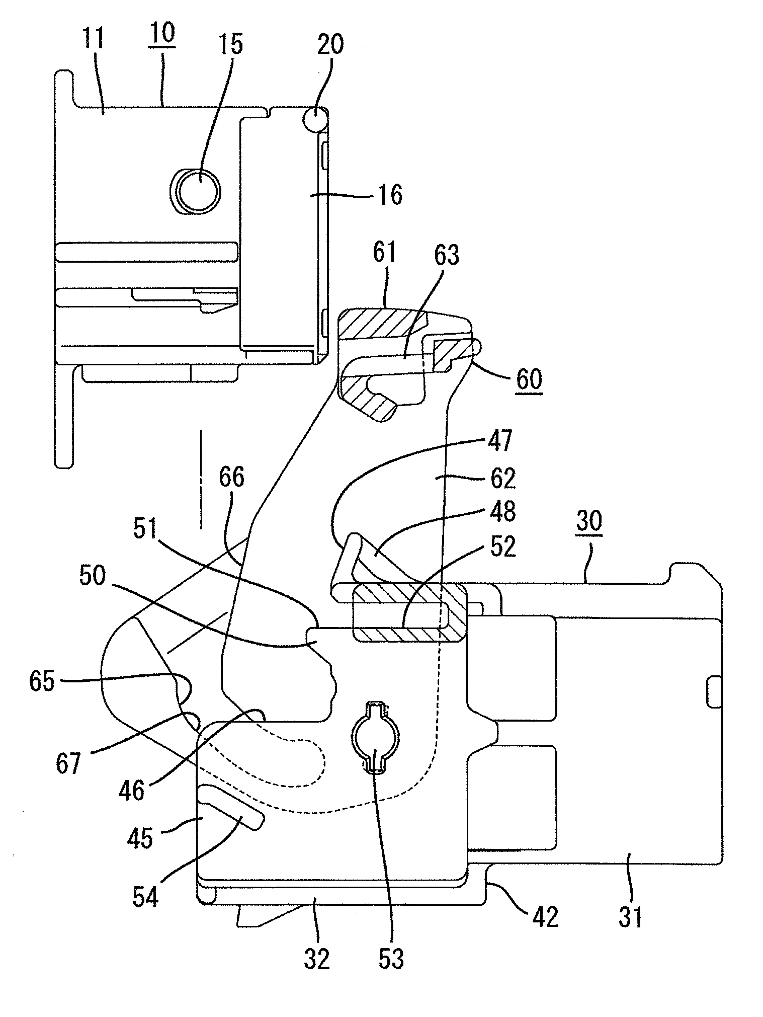
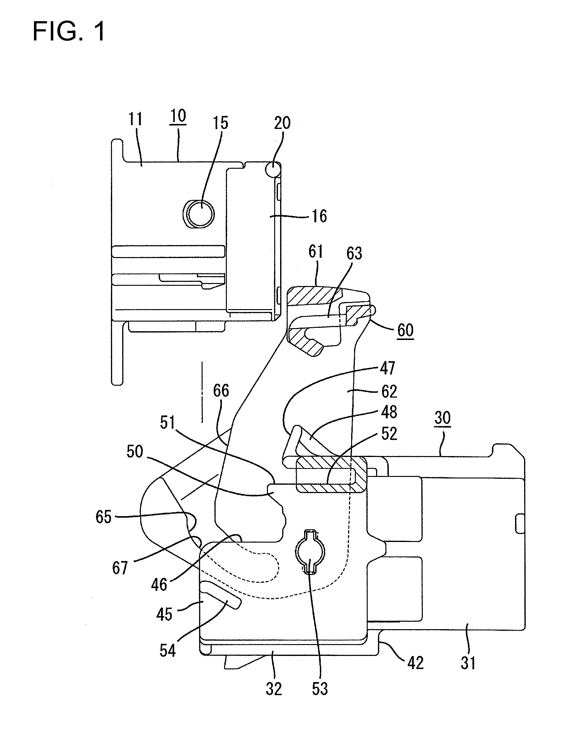
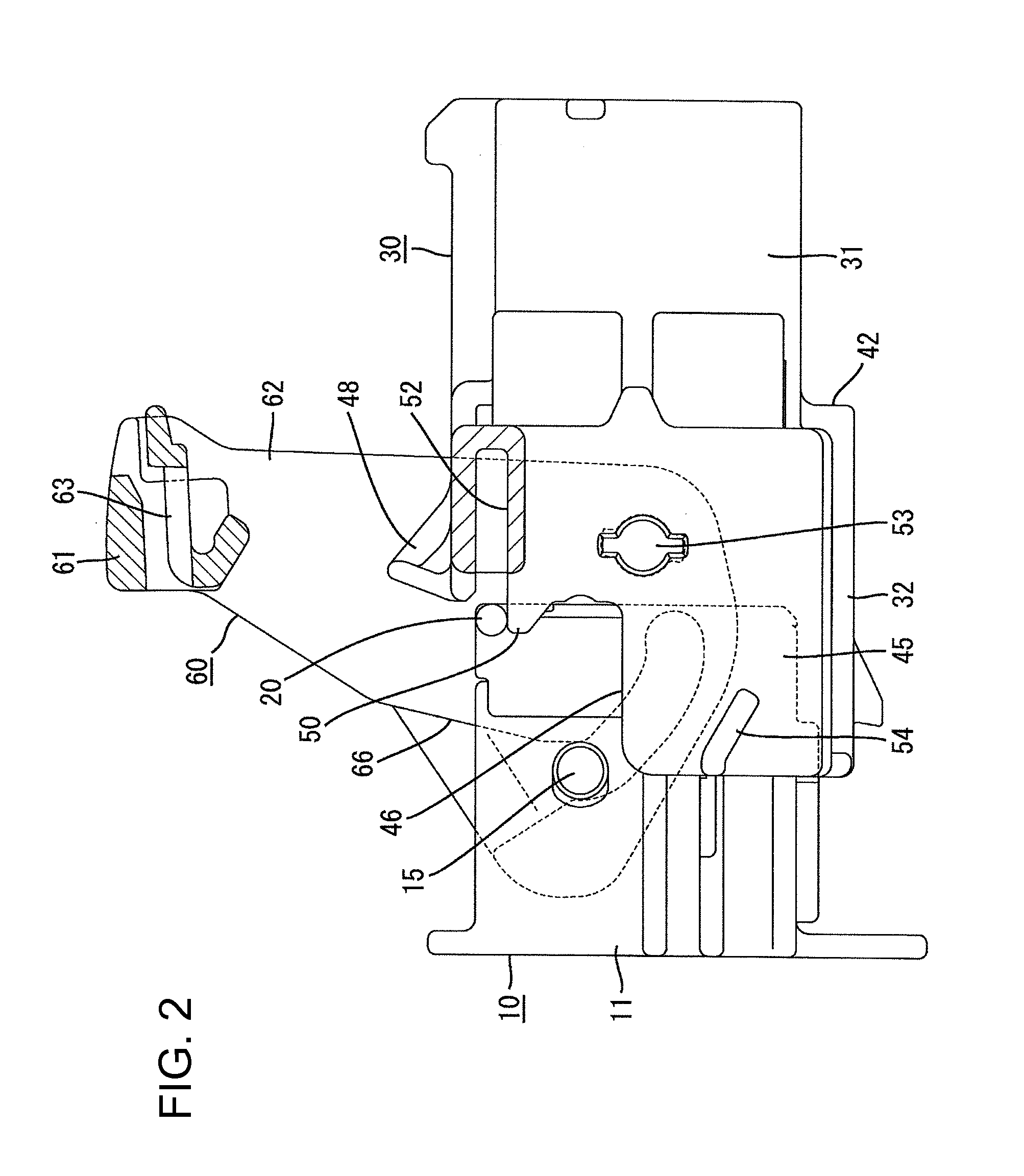
[0007]The invention relates to a lever connector with first and second housings that are engageable with each other. A lever is mounted on the first housing in a displaceable manner between an initial position and a fitting position. A cam groove is formed on the lever and a cam follower is formed on the second housing. The cam follower is introduced into the cam groove from an entrance of the cam groove by bringing the first and second housings into slight fitting engagement while holding the lever at the initial position. The cam follower is moved slidably on a groove surface of the cam groove by displacing the lever toward the fitting position. Thus, the first and second housings are brought into a normal fitting position due to a cam action exerted by the slide movement of the cam follower. The entrance of the cam groove is arranged in a direction that intersects the fitting direction of the first and second housings when the lever is at the initial position. Thus, the assembling direction of the second housing to the first housing intersects the fitting direction of the housings. Accordingly, a large assembling space is unnecessary in the fitting direction of the housings so that space efficiency is enhanced.
[0010]The cutaway portion is formed on the hood and the tab of the male terminal fitting projects inside of the hood. Thus, there is a possibility that the inclined second housing will break or damage the tab. However, the restriction contacts the interference portion to restrict insertion of the inclined second housing into the hood and to prevent the tab from being broken or damaged.
[0012]The lever may be arranged in a raised manner to project from the first housing and the entrance of the cam groove may be directed toward a lever projecting side when the lever is at the initial position. Thus, a space on the lever projecting side is used efficiently so that the connector exhibits excellent space efficiency.

Problems solved by technology

Thus, engagement of the second housing in the inclined posture into the inside of the hood is restricted.
Thus, there is a possibility that the inclined second housing will break or damage the tab.

Method used


Image

  • Lever connector
  • Lever connector
  • Lever connector

Examples


Embodiment Construction

[0024]A connector according to the invention has a male connector and a female connector that are engageable with each other. The female connector has a female housing 10 and the male connector has a male housing 30 and a lever 60. Ends of the connectors that are engaged with each other are referred to as the front ends herein.

[0025]The female housing 10 is made of a synthetic resin, and includes a quadrangular-block-shaped female housing body 11, as shown in FIG. 9. Cavities 12 extend longitudinally through the female housing body 11 and a deflectable lance 13 projects forwardly in each cavity 12. A deflection space 14 is formed below each lance 13 and opens at a front surface of the female housing body 11. As shown in FIG. 6, a female terminal fitting 80 is inserted into the inside of each cavity 12 from the rear and the lance 13 prevents removal of the properly inserted female terminal fitting 80.

[0026]The female terminal fitting 80 is formed by bending or otherwise forming a uni...


PUM


Abstract

A lever connector that exhibits excellent space efficiency is provided. The lever connector includes female and male housings that are engageable with each other. A lever is mounted displaceably on the male housing and can be moved between an initial position and a fitting position. A cam groove is formed on the lever, and a cam follower is formed on the female housing. An entrance of the cam groove is aligned in a direction that intersects the fitting direction of the housings when the lever is at the initial position, and the female housing is assembled into a hood along the same direction.

Description

BACKGROUND OF THE INVENTION[0001]1. Field of the Invention[0002]The invention relates to a lever connector.[0003]2. Description of the Related Art[0004]JP-A-2008-27787 discloses a conventional lever connector with first and second housings that are engageable with each other. A lever is mounted on the first housing for rotation between an initial position and a fitting position. A cam groove is formed on the lever, and a cam follower projects from the second housing. The first and second housings are engaged slightly while holding the lever at the initial position. Thus, the cam follower is introduced into the cam groove. The lever then is rotated toward the fitting position. As a result, the cam follower is moved slidably on a surface of the cam groove so that a cam action is exerted between the lever and the second housing. Accordingly, it is possible to bring the first and second housings into the fitting engagement with a low manipulation force.[0005]In the above-mentioned conve...

Claims


Application Information

Patent Timeline
Patent Type & Authority Applications(United States)
IPC IPC(8): H01R13/62
CPCH01R13/62972H01R13/62938
Inventor FUKAMACHI, MAKOTOKATSUMA, TAKATOSHI
Owner SUMITOMO WIRING SYST LTD
Learn More